Liquid discharging apparatus and control method thereof

a technology of liquid discharging apparatus and control method, which is applied in printing and other directions, can solve the problem that the bubbles in the circulating channel may not be sufficiently removed

Active Publication Date: 2013-12-03
SEIKO EPSON CORP
View PDF44 Cites 2 Cited by
  • Summary
  • Abstract
  • Description
  • Claims
  • Application Information

AI Technical Summary

Benefits of technology

[0006]An advantage of some aspects of the invention is to provide a liquid discharging apparatus and the control method thereof, which may more securely remove gas (bubbles) in a circulating path when liquid is filled in a discharging head.
[0009]In the liquid discharging apparatus of the present invention, when the discharging head is filled with a liquid, the first circulation control for controlling the pump unit so that an amount of liquid equal to or greater than the entire volume of the circulating path circulates from the one opening end portion side to the other opening end portion side via the discharging head (hereinafter, referred to as circulation in a forward direction) by the drive of the pump unit is executed, and after the first circulation control is executed, the second circulation control for controlling the pump unit so that the amount of liquid equal to or greater than the entire volume of the circulating path circulates from the other opening end portion side to the one opening end portion side via the discharging head (hereinafter, referred to as circulation in a reverse direction) by the drive of the pump unit is executed. Therefore, since the amount of liquid equal to or greater than the entire volume of the circulating path circulates along the circulating path in the forward direction and then the amount of liquid equal to or greater than the entire volume of the circulating path circulates along the circulating path in the reverse direction, even though the circulating path has a location where gas (bubbles) may easily stay when the liquid circulates along the circulating path in the forward direction, the liquid of the circulating path may be more securely removed.
[0010]The liquid discharging apparatus according to the present invention may further include an opening / closing valve installed at the other opening end portion side rather than the discharging head in the circulating path so as to be capable of opening / closing, and the charge time control unit may execute the first circulation control in a state where the opening / closing valve is open, then control the opening / closing valve so that the opening / closing valve is closed, control the pump unit so that a predetermined liquid which is at the one opening end portion side rather than the opening / closing valve in the circulating path is pumped to the one opening end portion side by the drive of the pump unit, control the opening / closing valve so that the opening / closing valve is opened, and then execute the second circulation control. By doing so, in the case where gas is present in the circulating path, it is possible to expand the gas (bubbles) in the circulating path by lowering the pressure at the predetermined portion, and the flow rate may be increased after the opening / closing valve is opened, so that the gas may be easily discharged to the storing unit. In the liquid discharging apparatus according to the present invention, after the first circulation control is executed and the one opening / closing valve is opened, the charge time control unit may execute a short-time first control for controlling the pump unit so that the liquid is pumped from the other opening end portion side to the one opening end portion side during a shorter time than the execution time of the second circulation control by the drive of the pump unit, and a short-time second control for controlling the pump unit so that the liquid is pumped from the one opening end portion side to the other opening end portion side by the drive of the pump unit during a shorter time than the execution time of the second circulation control after the short-time first control is executed, predetermined times, and then execute the second circulation control. By doing so, in the case where gas is present in the circulating path, the gas may be easily discharged to the storing unit by moving the gas to the one opening end portion side or the other opening end portion side.
[0011]In addition, in the liquid discharging apparatus according to the present invention, after the first circulation control is executed, the charge time control unit may execute a short-time first control for controlling the pump unit so that the liquid is pumped from the other opening end portion side to the one opening end portion side by the drive of the pump unit during a shorter time than the execution time of the second circulation control, and a short-time second control for controlling the pump unit so that the liquid is pumped from the one opening end portion side to the other opening end portion side by the drive of the pump unit during a shorter time than the execution time of the second circulation control after the short-time first control is executed, predetermined times, and then execute the second circulation control. By doing so, in the case where gas is present in the circulating path, the gas may be easily discharged to the storing unit by moving the gas to the one opening end portion side or the other opening end portion side.
[0012]Further the liquid discharging apparatus according to the present invention may further include a height adjustment unit capable of adjusting the height of at least one of the one opening end portion and the other opening end portion in the circulating path in a gravity direction, and the charge time control unit may control the height adjustment unit so that the one opening end portion is lower than the other opening end portion when the liquid circulates from the one opening end portion side to the other opening end portion side, and the charge time control unit may control the height adjustment unit so that the other opening end portion is lower than the one opening end portion when the liquid circulates from the other opening end portion side to the one opening end portion side. By doing so, it is possible to restrain gas from penetrating from the storing unit to the circulating path.
[0016]In the control method of a liquid discharging apparatus according to the present invention, when the discharging head is filled with a liquid, the first circulation control for controlling the pump unit so that an amount of liquid equal to or greater than the entire volume of the circulating path circulates from the one opening end portion side to the other opening end portion side via the discharging head (hereinafter, referred to as circulation in a forward direction) by the drive of the pump unit is executed, and after the first circulation control is executed, the second circulation control for controlling the pump unit so that the amount of liquid equal to or greater than the entire volume of the circulating path circulates from the other opening end portion side to the one opening end portion side via the discharging head (hereinafter, referred to as circulation in a reverse direction) by the drive of the pump unit is executed. Therefore, since the amount of liquid equal to or greater than the entire volume of the circulating path circulates along the circulating path in the forward direction and then the amount of liquid equal to or greater than the entire volume of the circulating path circulates along the circulating path in the reverse direction, even though the circulating path has a location where gas (bubbles) may easily stay when the liquid circulates along the circulating path in the forward direction, the liquid of the circulating path may be more securely removed.

Problems solved by technology

In the above liquid discharging apparatus, it is possible to prevent ink or bubbles from flowing backward, but in the case where the circulating channel has a location at which bubbles tend to stay (for example, a joint of each component of the circulating channel) when ink flows in a forward direction, the bubbles in the circulating channel may not be sufficiently removed.

Method used


Image

  • Liquid discharging apparatus and control method thereof
  • Liquid discharging apparatus and control method thereof
  • Liquid discharging apparatus and control method thereof

Examples


Embodiment Construction

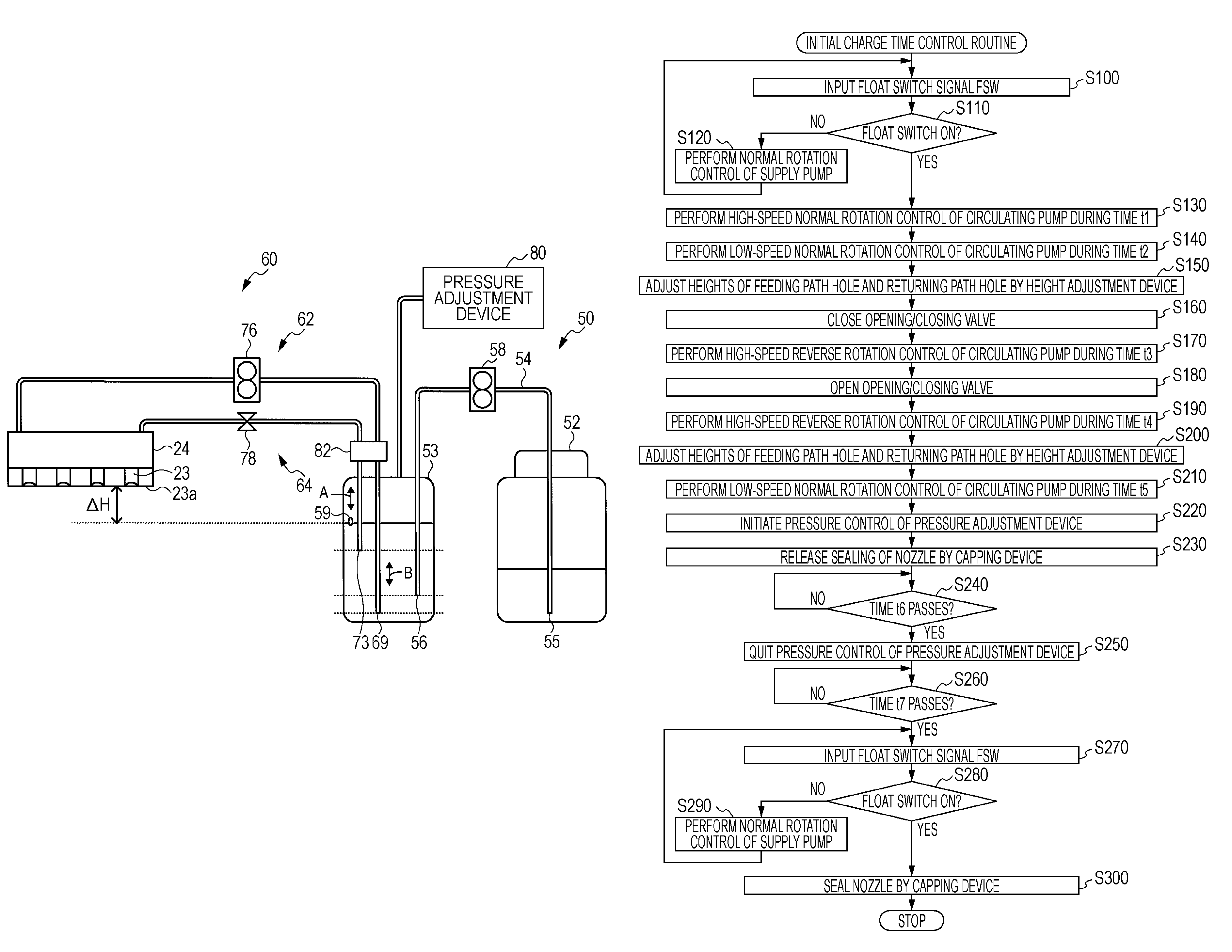
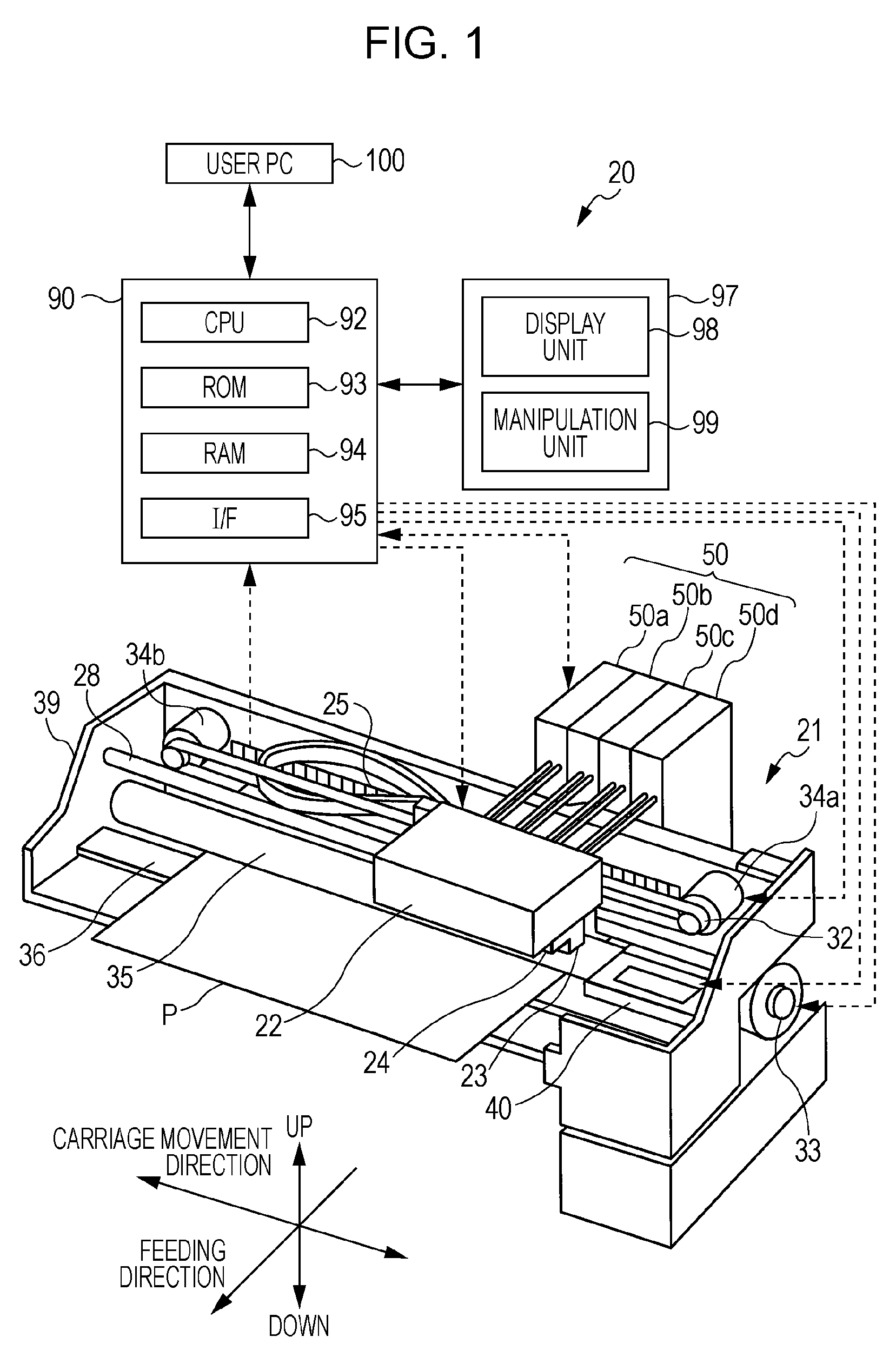
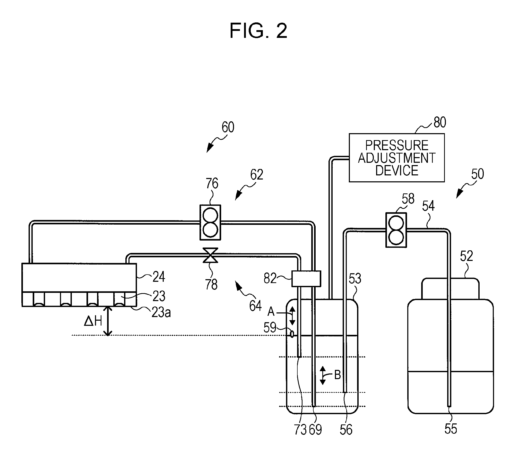
[0024]Next, an embodiment of the present invention will be described with reference to the drawings. FIG. 1 is a diagram schematically showing the configuration of an ink jet printer 20. FIG. 2 is a diagram schematically showing the configuration of an ink circulating system 50. FIG. 3 is a diagram schematically showing the configuration of a capping device 40.

[0025]The ink jet printer 20 of this embodiment includes, as shown in FIG. 1, a printer mechanism 21 for sending ink droplets from a plurality of nozzles 23 formed at a printing head 24 to a paper P fed on a platen 36 to perform printing, a capping device 40 disposed near the right end of the platen 36 and capable of independently sealing the plurality of nozzles 23 of the printing head 24, a controller 90 for controlling the entire apparatus, and a manipulation panel 97 having a display unit 98 for notifying various kinds of information to a user or a manipulation unit 99 allowing a user to input various instructions.

[0026]Th...


PUM


Abstract

When a printing head is filled with an ink, a circulating pump is controlled so that an ink equal to or greater than the entire volume of a circulating path circulates from a feeding path hole to a returning path hole via a printing head (in a forward direction), and after that, the circulating pump is controlled so that the ink equal to or greater than the entire volume of the circulating path circulates from the returning path hole to the feeding path hole via the printing head (in a reverse direction). By doing so, gas (bubbles) in the circulating path may be more securely discharged to a sub tank.

Description

BACKGROUND[0001]1. Technical Field[0002]The present invention relates to a liquid discharging apparatus and a control method thereof.[0003]2. Related Art[0004]Heretofore, as such a kind of liquid discharging apparatus, an apparatus has been proposed including a printing head for ejecting ink, an ink tank accommodating the ink, a first ink channel for supplying the ink from the ink tank to a manifold of the printing head, a second ink channel for retrieving the ink from the manifold to the ink tank, an ink circulating pump installed at the first ink channel, an opening / closing valve installed at the second ink channel, a suction cap for covering nozzle surface of the printing head, and a suction pump connected to the suction cap via a suction pipe, wherein, when the ink is filled in the printing head, the nozzle surface of the printing head is covered by the suction cap and the opening / closing valve opens to rotatably drive the ink circulating pump, so that the ink circulates through...

Claims


Application Information

Patent Timeline
Patent Type & Authority Patents(United States)
IPC IPC(8): B41J2/175B41J2/19
CPCB41J2/175B41J2/17596B41J2/18
Inventor KOIKE, KAORUKUMAGAI, TOSHIO
Owner SEIKO EPSON CORP
Why Eureka
Try Eureka