Eccentric abrading head for high-speed rotational atherectomy devices

a technology of atherectomy and abrading head, which is applied in the field of eccentric abrading head for high-speed rotational atherectomy devices, can solve the problems of stent restenosis, block blood flow, and angina, and achieve the effects of reducing the risk of stroke, and improving the effect of abrading head

Active Publication Date: 2013-12-03
CARDIOVASCULAR SYST INC
View PDF61 Cites 58 Cited by
  • Summary
  • Abstract
  • Description
  • Claims
  • Application Information

AI Technical Summary

Benefits of technology

[0011]The invention provides a rotational atherectomy device having, in various embodiments, a flexible, elongated, rotatable drive shaft with at least one flexible eccentric enlarged abrading head attached thereto. In other embodiments, the eccentric abrading head is not flexible or partially flexible. At least part of the eccentric enlarged cutting head has a tissue removing surface—typically an abrasive surface. In certain embodiments, the abrading head will be at least partially hollow. When placed within an artery against stenotic tissue and rotated at sufficiently high speeds the eccentric nature of the enlarged cutting head causes the cutting head and drive shaft to rotate in such a fashion as to open the stenotic lesion to a diameter substantially larger than the outer diameter of the enlarged cutting head. Preferably the eccentric enlarged cutting head has a center of mass spaced radially from the rotational axis of the drive shaft, facilitating the ability of the device to open the stenotic lesion to a diameter substantially larger than the outer diameter of the enlarged cutting head when operated at high speeds.
[0016]Another object of the invention is to provide a high-speed rotational atherectomy device having at least one flexible eccentric cutting head that flexes during insertion and placement, providing an improved ability to navigate tortuous lumens with minimal trauma.
[0017]Another object of the invention is to provide a high-speed rotational atherectomy device having at least one non-flexible eccentric cutting head that does not flex during operation, providing the operator with an improved degree of control over the cutting head's orbital diameter.

Problems solved by technology

If left untreated, such stenoses can cause angina, hypertension, myocardial infarction, strokes and the like.
Studies have shown, however, that a significant percentage of patients who have undergone balloon angioplasty and had a stent placed in an artery experience stent restenosis—i.e., blockage of the stent which most frequently develops over a period of time as a result of excessive growth of scar tissue within the stent.
As the burr is removing stenotic tissue, however, it blocks blood flow.
This flexion allows for a larger diameter opening during high speed operation, but may also provide less control than desired over the diameter of the artery actually abraded.
In addition, some stenotic tissue may block the passageway so completely that the Shturman device cannot be placed therethrough.
Since Shturman requires that the enlarged eccentric section of the drive shaft be placed within the stenotic tissue to achieve abrasion, it will be less effective in cases where the enlarged eccentric section is prevented from moving into the stenosis.
This construction is limited, however because, as Clement explains at Col. 3, lines 53-55, that the asymmetrical burr is rotated at “lower speeds than are used with high speed ablation devices, to compensate for heat or imbalance.” That is, given both the size and mass of the solid burr, it is infeasible to rotate the burr at the high speeds used during atherectomy procedures, i.e., 20,000-200,000 rpm.
Essentially, the center of mass offset from the rotational axis of the drive shaft would result in development of significant centrifugal force, exerting too much pressure on the wall of the artery and creating too much heat and excessively large particles.

Method used


Image

  • Eccentric abrading head for high-speed rotational atherectomy devices
  • Eccentric abrading head for high-speed rotational atherectomy devices
  • Eccentric abrading head for high-speed rotational atherectomy devices

Examples


Embodiment Construction

[0044]While the invention is amenable to various modifications and alternative forms, specifics thereof are shown by way of example in the drawings and described in detail herein. It should be understood, however, that the intention is not to limit the invention to the particular embodiments described. On the contrary, the intention is to cover all modifications, equivalents, and alternatives falling within the spirit and scope of the invention.

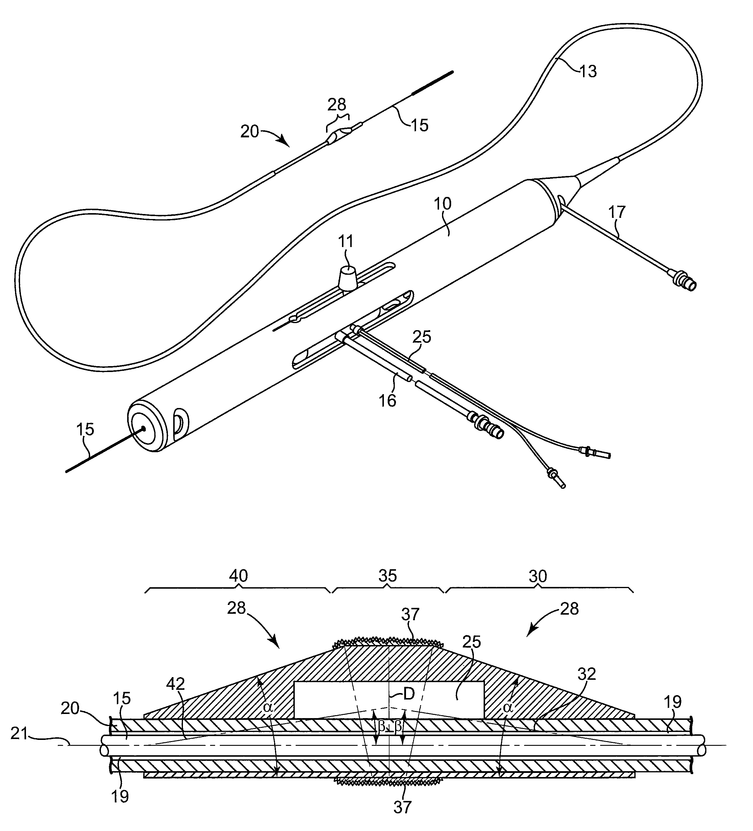
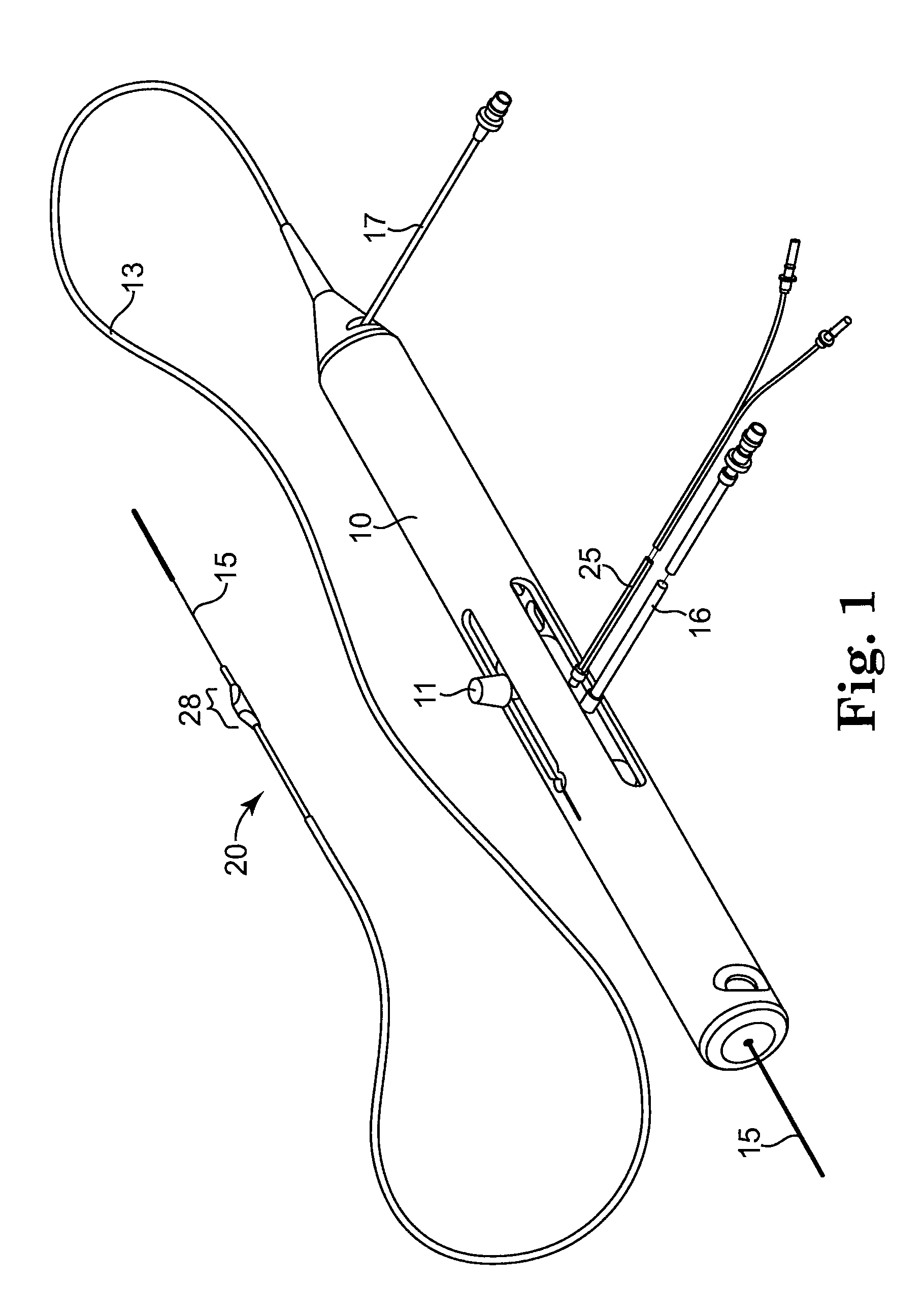
[0045]FIG. 1 illustrates one embodiment of a rotational atherectomy device according to the present invention. The device includes a handle portion 10, an elongated, flexible drive shaft 20 having an eccentric enlarged abrading head 28, and an elongated catheter 13 extending distally from the handle portion 10. The drive shaft 20 is constructed from helically coiled wire as is known in the art and the abrading head 28 is fixedly attached thereto. The catheter 13 has a lumen in which most of the length of the drive shaft 20 is disposed, except...


PUM


Abstract

The invention provides a rotational atherectomy device having, in various embodiments, a flexible, elongated, rotatable drive shaft with at least one flexible eccentric enlarged abrading head attached thereto. In other embodiments, the eccentric abrading head is not flexible or partially flexible. At least part of the eccentric enlarged cutting head has a tissue removing surface—typically an abrasive surface. In certain embodiments, the abrading head will be at least partially hollow. When placed within an artery against stenotic tissue and rotated at sufficiently high speeds the eccentric nature of the enlarged cutting head causes the cutting head and drive shaft to rotate in such a fashion as to open the stenotic lesion to a diameter substantially larger than the outer diameter of the enlarged cutting head. Preferably the eccentric enlarged cutting head has a center of mass spaced radially from the rotational axis of the drive shaft, facilitating the ability of the device to open the stenotic lesion to a diameter substantially larger than the outer diameter of the enlarged cutting head when operated at high speeds.

Description

BACKGROUND OF THE INVENTION[0001]1. Field of the Invention[0002]The invention relates to devices and methods for removing tissue from body passageways, such as removal of atherosclerotic plaque from arteries, utilizing a high-speed rotational atherectomy device.[0003]2. Description of the Related Art[0004]A variety of techniques and instruments have been developed for use in the removal or repair of tissue in arteries and similar body passageways. A frequent objective of such techniques and instruments is the removal of atherosclerotic plaques in a patient's arteries. Atherosclerosis is characterized by the buildup of fatty deposits (atheromas) in the intimal layer (under the endothelium) of a patient's blood vessels. Very often over time, what initially is deposited as relatively soft, cholesterol-rich atheromatous material hardens into a calcified atherosclerotic plaque. Such atheromas restrict the flow of blood, and therefore often are referred to as stenotic lesions or stenoses,...

Claims


Application Information

Patent Timeline
Patent Type & Authority Patents(United States)
IPC IPC(8): A61B17/22
CPCA61B17/320758A61B2017/22038A61B2017/320004A61B2017/320766A61B17/22012
Inventor THATCHER, ROBERT J.ROBINSON, PAUL J.
Owner CARDIOVASCULAR SYST INC
Why Eureka
Try Eureka