Ergonomic and space-saving arrangement of monuments underneath a rest compartment in an aircraft

a technology for rest compartments and aircraft, which is applied in the direction of seat arrangements, aircraft crew accommodation, emergency apparatus, etc., can solve the problems of severely limiting the comfort of passengers in the aircraft cabin, the space situated underneath cannot be used for other than passenger seats or partition walls, and the width of the toilet wall in the seat region is considerably reduced, and the comfort of passengers present in the toilet is not diminished. , the effect of reducing the width of the toilet wall

Active Publication Date: 2013-12-10
AIRBUS OPERATIONS GMBH
View PDF8 Cites 18 Cited by
  • Summary
  • Abstract
  • Description
  • Claims
  • Application Information

AI Technical Summary

Benefits of technology

[0008]As a result of the arrangement of the toilet and the rest compartment according to the invention with a lowered passage it is possible to optimally use the space available in the cabin without, however, diminishing the ergonomics and the comfort. Furthermore, this results in the potential for obtaining additional stowage space, and the monuments within the cabin in the rest compartment region are arranged in a space-saving manner so that the flexibility relating to the cabin design can be improved.

Problems solved by technology

For this reason the walls at the bottom of the rest compartment, which walls delimit the passage, are relatively pronounced, and consequently the space situated underneath it can hardly be used for installations other than passenger seats or partition walls.
Larger monuments, for example aircraft toilets, which are arranged in centre regions of the cabin and which are designed in the conventional, essentially cuboid, manner, cannot be integrated underneath such a rest compartment because their design heights are such that the passage of the rest compartment would project into toilet compartments situated below it.
As a result of this the toilet compartments could only be used with the user stooping therein, which would, however, severely limit passenger comfort within the aircraft cabin.

Method used


Image

  • Ergonomic and space-saving arrangement of monuments underneath a rest compartment in an aircraft
  • Ergonomic and space-saving arrangement of monuments underneath a rest compartment in an aircraft
  • Ergonomic and space-saving arrangement of monuments underneath a rest compartment in an aircraft

Examples


Embodiment Construction

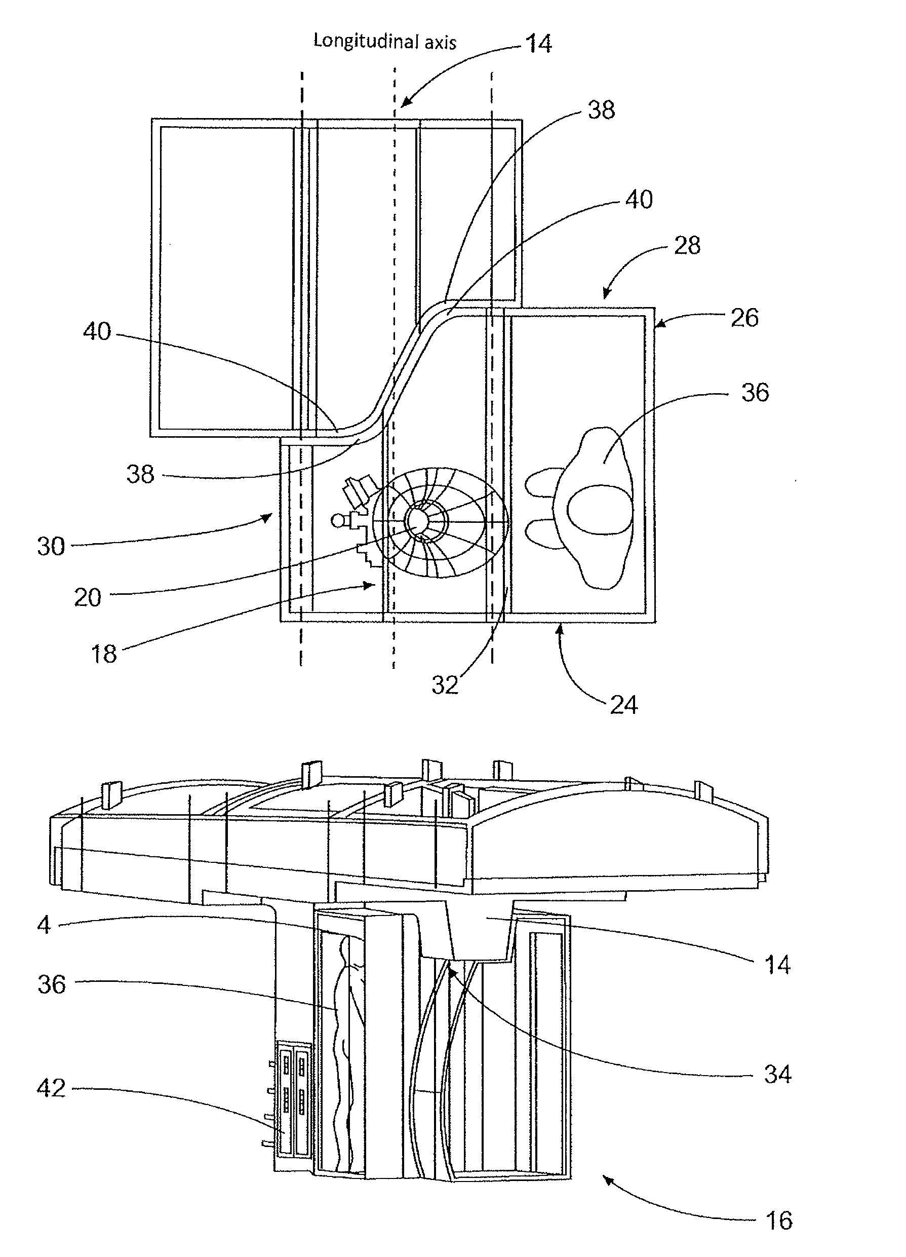
[0014]FIG. 1 shows a basic principle of a rest compartment in an aircraft cabin. On the left-hand side there is a first berth 2, which can, for example, be reached through an ascent 4 by way of steps 6. The ascent 4 can, for example, comprise an intermediate level 8 below which additional stowage space could be created that is, for example, suitable for accommodating trolleys. On the right-hand side of FIG. 1 a second berth 10 is positioned which can, for example, be reached by way of a passage 14 that is lowered relative to the floor 12. In this arrangement it is possible to walk along the passage 14 in a stooped position in order to reach the second berth 10. Since the passage 14 projects downward into the cabin it is not possible to position conventional toilets in this region because the normal design height of a toilet would require a greater space height than only up to the underside of the passage 14.

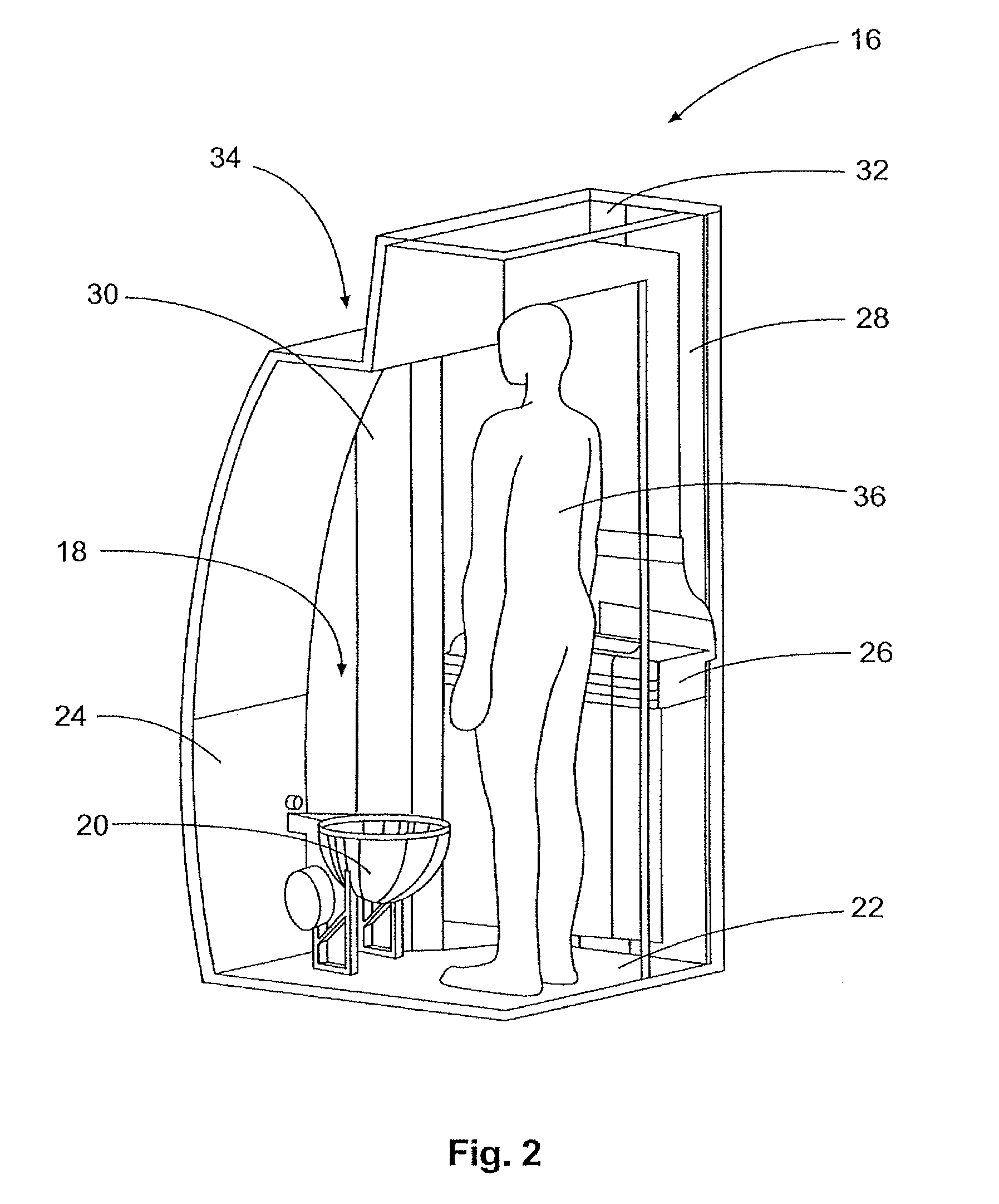
[0015]For this reason the toilets 16 that are designed as shown in FIG. 2 ar...


PUM


Abstract

The invention relates to a rest compartment arrangement in an aircraft, comprising a rest compartment and at least one monument, wherein the rest compartment is arranged above a cabin floor and comprises a passage that extends from a rest compartment floor in the direction of the cabin floor. When compared to the state of the art, the invention is characterized in that the at least one monument comprises at least one wall which above a seat region situated therein forms a recess to accommodate the passage. As a result of this, monuments can be positioned in a space-saving manner underneath the passage in the cabin without this resulting in reduced comfort, because the recess above the seat region is not perceived to be distracting by the passenger.

Description

CROSS-REFERENCE TO RELATED APPLICATIONS[0001]The present application is a national phase entry under 35 U.S.C. §371 of International Application No. PCT / EP2009 / 052861, filed Mar. 11, 2009, published in German, which claims the benefit of the filing date of U.S. Provisional Patent Application No. 61 / 070,892 filed Mar. 26, 2008 and of German Patent Application No. 10 2008 015 788.0 filed Mar. 26, 2008, the disclosure of which applications is hereby incorporated herein by reference.TECHNICAL FIELD OF THE INVENTION[0002]The invention relates to a rest compartment arrangement in an aircraft.TECHNOLOGICAL BACKGROUND OF THE INVENTION[0003]Rest compartments in an aircraft are already well known; in long-haul flights of relatively long flight duration they are used as rest areas by members of the on-board crew. Rest compartments can be positioned at various places within the aircraft, which depends, in particular, on the respective aircraft type or on its size. For example, rest compartments...

Claims


Application Information

Patent Timeline
Patent Type & Authority Patents(United States)
IPC IPC(8): B64D11/06
CPCB64D11/02B64D2011/0046
Inventor SUTTHOFF, THOMASBREUER, MATTHIASHELFRICH, FELIX
Owner AIRBUS OPERATIONS GMBH
Why Eureka
Try Eureka