

Device latch hook and attachment device including the same
a technology of device latch and attachment device, which is applied in the direction of snap fasteners, coupling device connections, sport apparatus, etc., can solve the problems of difficult to increase the size of the hook, improve the strength of the hook, and the hook is likely to be broken, so as to reduce the possibility of the ring portion being broken, prevent the ring portion from being broken, and improve the impact resistance of the hook
Inactive Publication Date: 2013-12-10
NINTENDO CO LTD
View PDF33 Cites 0 Cited by
- Summary
- Abstract
- Description
- Claims
- Application Information
AI Technical Summary
Benefits of technology
Problems solved by technology
In the case of the conventional hook, when a strong impact is applied to the electronic apparatus and the attachment device, a strong force is applied to the hook, and as a result, the hook is likely to be broken.
Particularly in the case of a hand-held device, since the device needs to be downsized, it is difficult to increase a size of the hook in order to improve strength of the hook.
On the other hand, since the hand-held device is portable, it is highly likely that the hand-held device is subject to a strong impact.
Method used
View moreImage
Smart ImageViewing Examples

Examples
first modified embodiment
[0046]FIG. 16 is a diagram showing a ring portion 21 of the hook 14 according to a
second modified embodiment
[0047]FIG. 17 is a diagram showing the ring portion 21 of the hook 14 ;
[0048]FIG. 18 is a diagram showing a configuration of a partition wall 34 according to another embodiment; and
[0049]FIG. 19 is a diagram showing a case where, in the configuration shown in FIG. 18, the hook 14 abuts against the partition wall 34.
Login to View More PUM
 Abstract
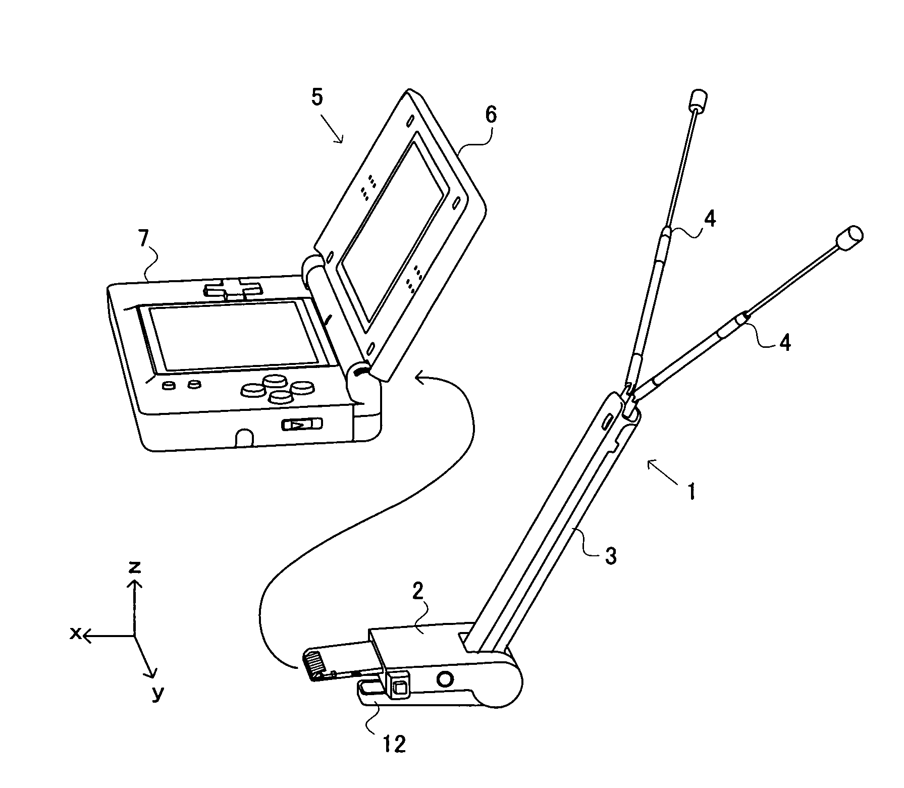
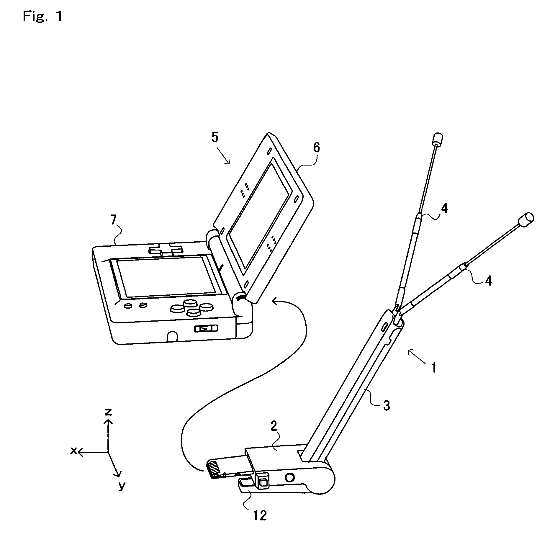
A hook 14 causes an attachment device (cartridge), which is mounted into an insertion slot arranged in an electronic apparatus such as a game apparatus, to be engaged with the insertion slot. The hook includes an arm 22, a ring portion 21 and a latch portion 23. The ring portion 21 is connected to one end of the arm 22. The latch portion 23 is connected to the other end of the arm 22, and is latchable onto a predetermined portion of the insertion slot. Further, the ring portion 21 is pivoted by a spindle 31 of the attachment device, and is shaped so as to be deformable when a force from the arm 22 is applied thereto, the force being caused by the attachment device moving so as to be ejected from the insertion slot.
Description
CROSS REFERENCE TO RELATED APPLICATION[0001]The disclosure of Japanese Patent Application No. 2007-238071, filed Sep. 13, 2007, is incorporated herein by reference.BACKGROUND OF EXAMPLE EMBODIMENTS OF THE INVENTION[0002]1. Field of Example Embodiments of the Invention[0003]Example embodiments of the present invention relate to a device latch hook, an attachment device and an electronic apparatus system. Example embodiments of the present invention more particularly relate to a device latch hook provided to an attachment device so as to prevent the attachment device which is inserted in an insertion slot of an electronic apparatus from being disengaged from the insertion slot, and the attachment device and an electronic apparatus system which include the device latch hook.[0004]2. Description of the Background Art[0005]Conventionally, a mechanism for mounting an attachment device such as a memory card into an electronic apparatus such as a hand-held device has been developed. For exa...
Claims
Login to View More Application Information
Patent Timeline
 Patent Type & AuthorityPatents(United States)
IPC IPC(8): E05C19/10A44B99/00H01R12/73
CPCA63F13/02A63F2300/1043Y10T24/44291Y10T24/44342Y10T292/0911Y10T292/1051A63F13/98
InventorKAMADA, HIROSHIYONEYAMA, KAZUOAMANO, MASAKI
OwnerNINTENDO CO LTD