
Wall-mounting structure for wall-mounted electronic device

a technology for electronic devices and mounting structures, which is applied in the direction of electrical apparatus casings/cabinets/drawers, instruments, cooling/ventilation/heating modifications, etc., can solve the problems of wasting labor and time, complicated disassembly procedures, etc., and achieves convenient disassembly and installation, quick cleaning and troubleshooting, and convenient mounting and disassembly.

Inactive Publication Date: 2013-12-10
ADLINK TECH INC
View PDF12 Cites 13 Cited by
  • Summary
  • Abstract
  • Description
  • Claims
  • Application Information

AI Technical Summary

Benefits of technology

Facilitates quick and tool-free mounting and dismounting of electronic devices, reducing installation and maintenance time, and allowing for efficient cleaning and troubleshooting without the need for tools.

Problems solved by technology

However, due to limited internal space, the arrangement of electronic components in a server must be well designed, leaving the necessary space for plugging / unplugging of bus lines.
This dismounting procedure is complicated, wasting much labor and time.

Method used


Image

  • Wall-mounting structure for wall-mounted electronic device
  • Wall-mounting structure for wall-mounted electronic device
  • Wall-mounting structure for wall-mounted electronic device

Examples


Embodiment Construction

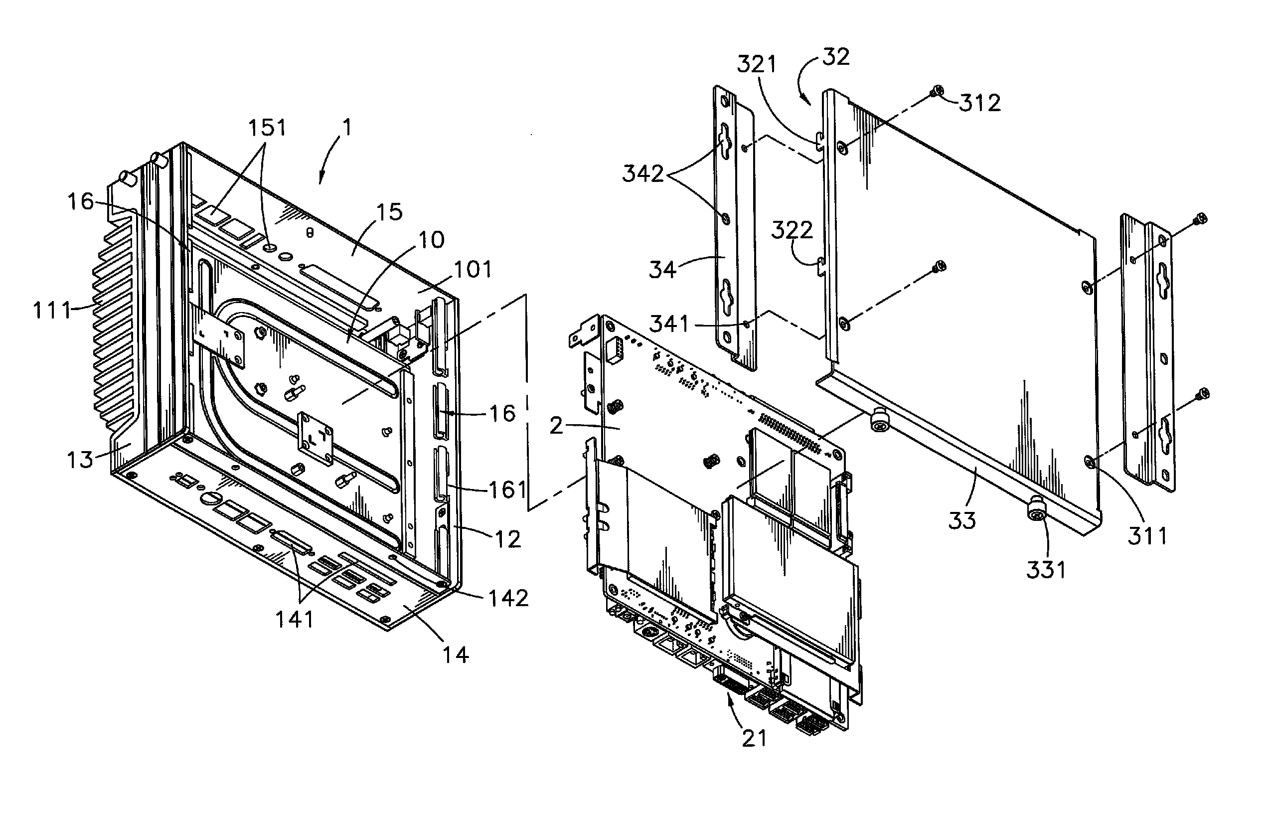
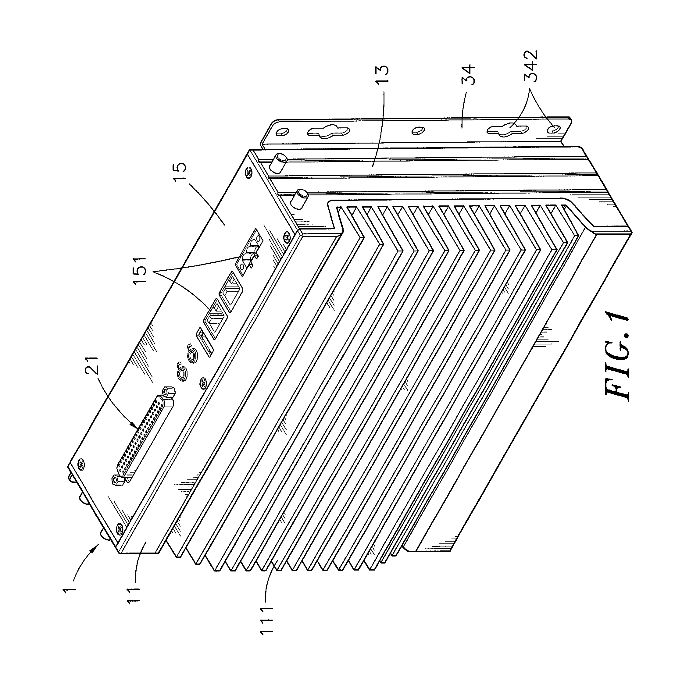
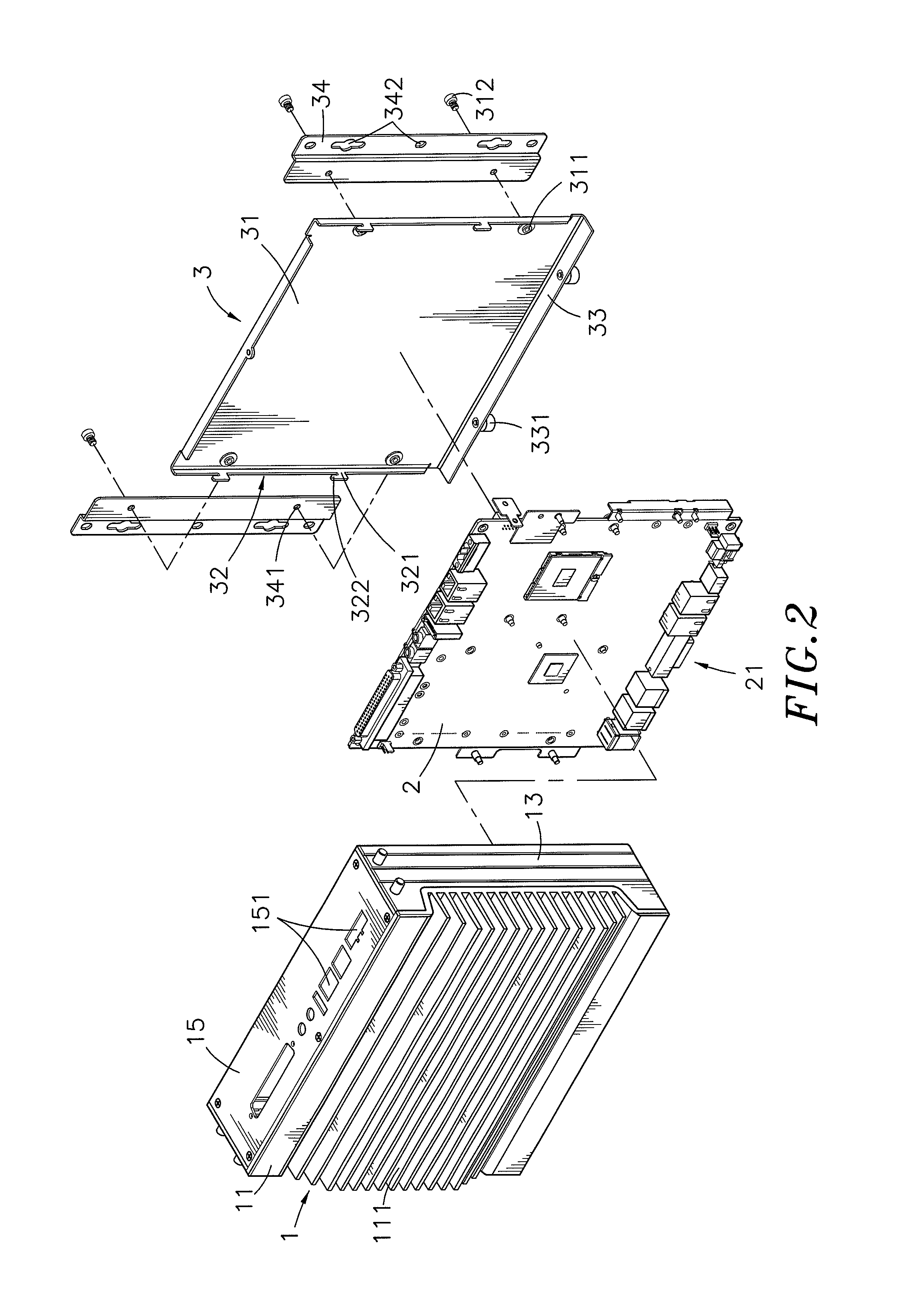
[0021]Referring to FIGS. 1, 2 and 3, a wall mounting structure for wall-mounted electronic device in accordance with the present invention is shown. The wall-mounting structure comprises a device shell 1, a circuit board 2, and a back cover 3.

[0022]The device shell 1 comprises a front panel 11, two opposing side panels 12 and 13 respectively perpendicularly extended from two opposing lateral sides of the front panel 11 in a parallel manner, opposing top panel 15 and bottom panel 14 respectively perpendicularly extended from opposing top and bottom sides of the front panel 11 in a parallel manner and respectively connected to opposing top and bottom sides of the side panels 12 and 13, an accommodation open chamber 10 surrounded by the front panel 11, the side panels 12 and 13, the top panel 15 and the bottom panel 14 and defining a back opening 101 opposite to the front panel 11, and a coupling structure 16 located on the side panels 12 and 13 at an inner side inside the accommodatio...


PUM


Abstract

A wall mounting structure for wall-mounted electronic device includes a device shell having a coupling structure disposed in an accommodation open chamber therein at two opposite lateral sides, a circuit board mounted in the accommodation open chamber, a cover plate having sliding coupling rods respectively extended from two side flanges thereof and detachably coupled to the coupling structure of the device shell and a bottom flange attached to the bottom side of the device shell to support the device shell, and two mounting brackets affixed to the cover plate at two opposite lateral sides for fastening to a wall of an external object.

Description

BACKGROUND OF THE INVENTION[0001]1. Field of the Invention[0002]The present invention relates wall-mounted electronic device mounting technology and more particularly, to a wall mounting structure for wall-mounted electronic device, which facilitates mounting and dismounting without any tools, saving much installation labor and time and allows quick cleaning and troubleshooting.[0003]2. Description of the Related Art[0004]In the computer and information era, many different electronic products have been created to serve people. Following progress of innovation activities in technology, multipurpose has become the mainstream of computer-controlled electronic products. In modern electronic products, computer plays the main role.[0005]As an advanced microprocessor for computer has great power, the use of an advanced microprocessor in a computer allows expansion of hardware devices, such as hard disk drives, CD-ROMs and programmers. A server for industrial computer generally comprises a ...

Claims


Application Information

Patent Timeline
Patent Type & Authority Patents(United States)
IPC IPC(8): H05K7/20
CPCG06F1/182H05K5/0204
Inventor CHAO, YUNG-JUI
Owner ADLINK TECH INC
Learn More