Injection valve with indexing mechanism

a technology of indexing mechanism and injection valve, which is applied in the direction of valve operating means/release devices, sealing/packing, and borehole/well accessories, etc., and can solve the problems of additional expense and operational problems

Active Publication Date: 2013-12-17
BAKER HUGHES INC
View PDF17 Cites 17 Cited by
  • Summary
  • Abstract
  • Description
  • Claims
  • Application Information

AI Technical Summary

Problems solved by technology

These designs such as the MC Injection Valves from Halliburton and the A Series Injection Valve from Schlumberger restrict access through the valve for advancing other tools.
While a dual control line system can offset this hydrostatic effect in deep applications there is additional expense and operational issues from doubling up the control lines and running them with a string into the subterranean location.

Method used


Image

  • Injection valve with indexing mechanism
  • Injection valve with indexing mechanism
  • Injection valve with indexing mechanism

Examples


Embodiment Construction

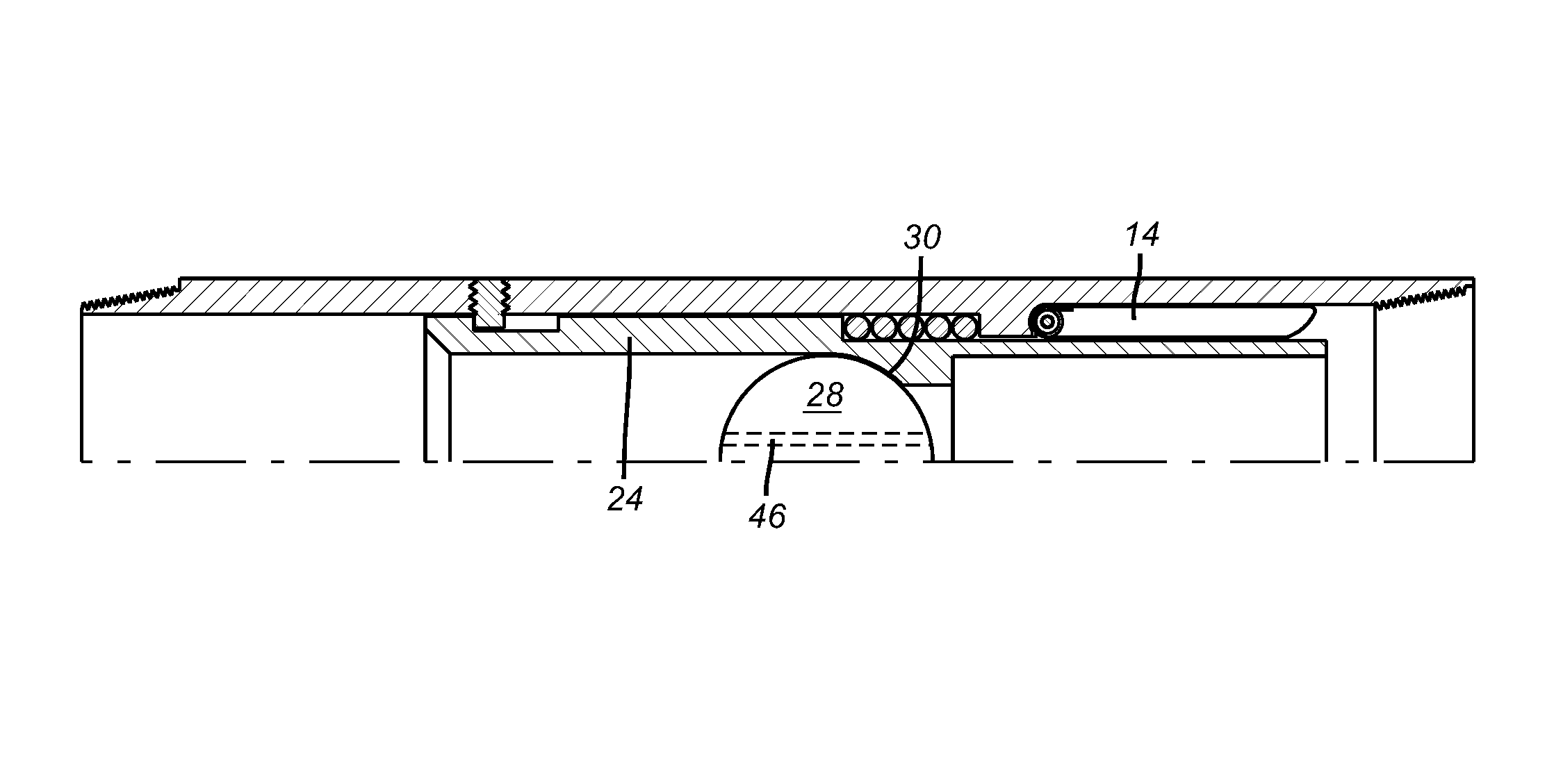
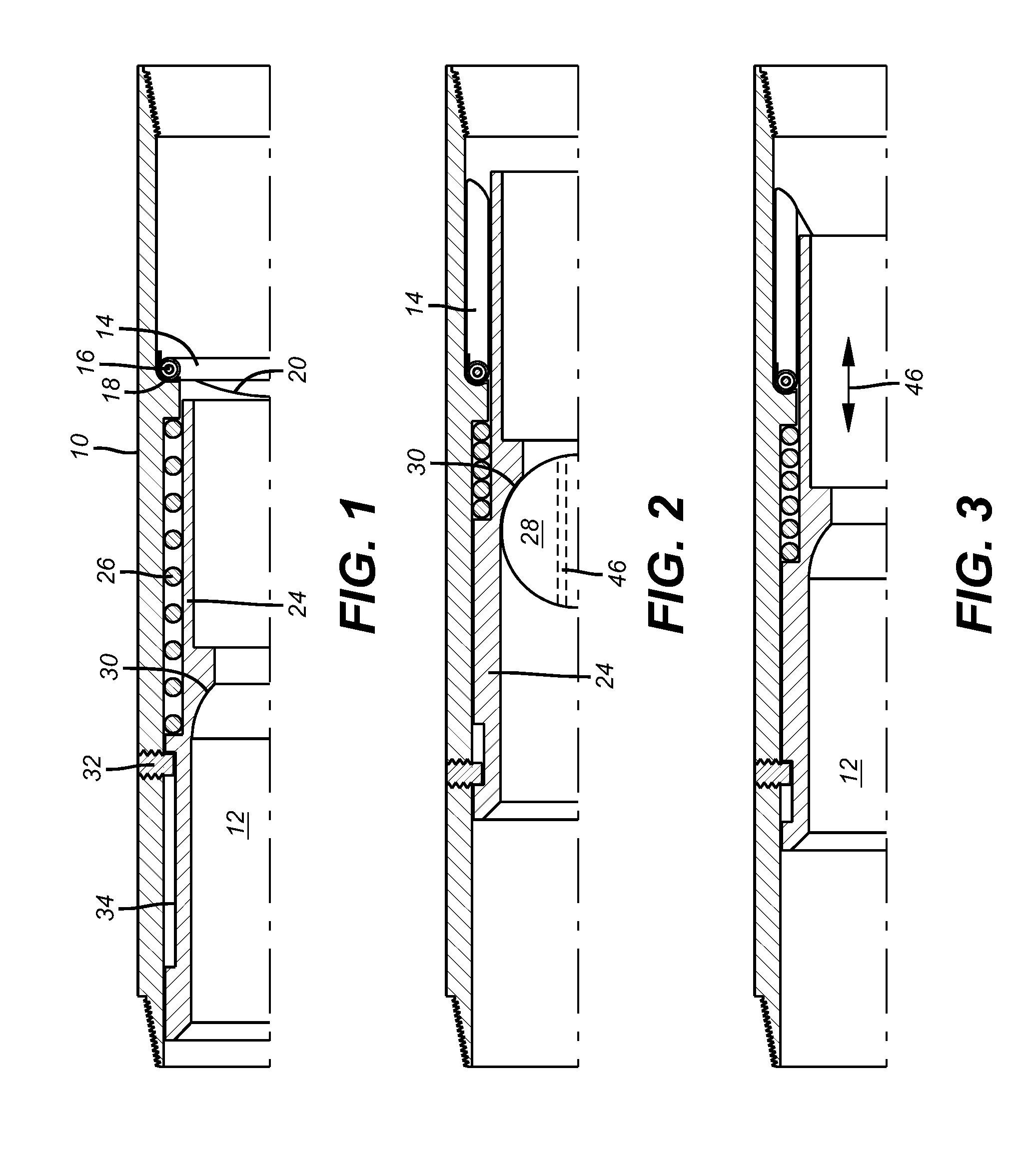
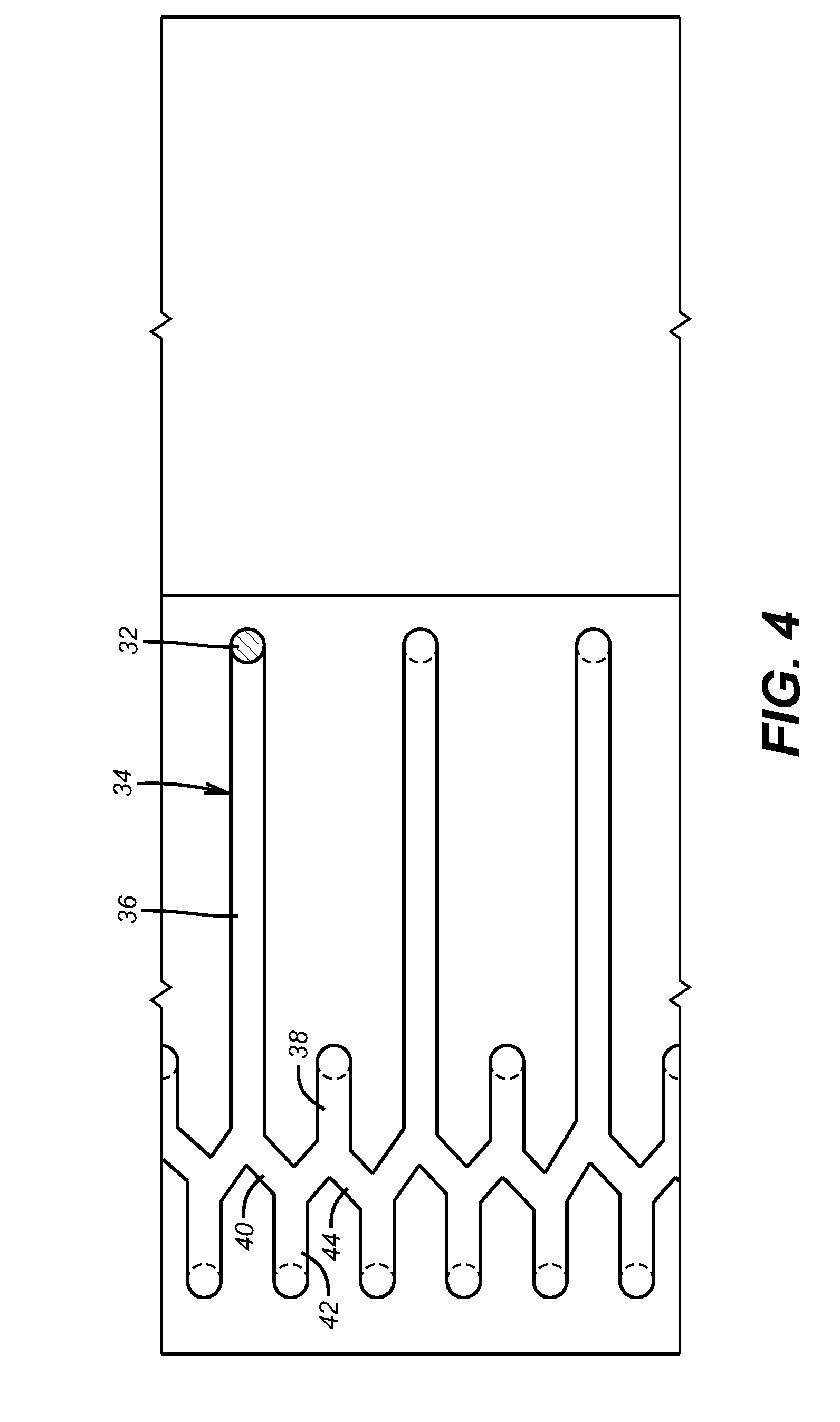
[0019]FIG. 1 has a housing 10 with a passage 12 and a flapper 14 that pivots on a pin 16. A torsion spring 18 biases the flapper 14 toward the closed position against the seat 20. An actuating sleeve 24 is slidably mounted in the passage 12 to move against the bias of a return spring 26 when an object such as a ball or plug 28 lands and obstructs the passage 12 at seat 30 as shown in FIG. 2. A pin or screw 32 extends into a j-slot track 34 that is shown rolled open in FIG. 4. The j-slot track 34 has a series of long passages 36 and short passages 38 that alternate. In the FIG. 1 position, the actuating sleeve 24 is at its highest location where spring 26 is extended and the flapper 14 is biased by spring 18 against the seat 20. This can happen because the actuating sleeve 24 in FIG. 1 is not in contact with the flapper 14. In essence the spring 26 advances the actuating sleeve 24 until the long passage 36 hits the pin 32, as shown in FIG. 1.

[0020]Dropping the object 28 onto seat 30 ...


PUM


Abstract

A flapper valve preferably used in injection application in deep subterranean locations has an actuating sleeve with a seat to accept an object. A j-slot connects the actuation sleeve movement to the housing so that with an object on the seat and an applied pressure cycle the sleeve moves the flapper to the open position. The plug is dissolved and the injection begins. The plug can have an opening so as to allow continuous injection flow as the flapper is operated. Closing the flapper involves a second object on the same seat and a pressure cycle so that a spring can push the sleeve away from the flapper to allow a torsion spring on the flapper to close it.

Description

FIELD OF THE INVENTION[0001]The field of this invention is valves for subterranean use that are actuated with an indexing mechanism and more particularly flapper type valves actuated with pressure cycles on a plug that can be removed after use.BACKGROUND OF THE INVENTION[0002]Various valve designs used in the past have incorporated sleeves indexed by j-slot devices to selectively align and misalign ports. In one example the ball that lands on a seat to allow application of pressure cycles to operate the j-slot is blown through the seat after a change in valve position. This is illustrated in U.S. Pat. No. 7,416,029. Another device is in essence a sliding sleeve that allows flow uphole and the sleeve, which is mounted to a j-slot, can be cycled from uphole as flow from uphole acts to close a flapper on top of the sleeve for pressure cycling. This is shown in US Publication 2008 / 0196898.[0003]Other designs use a j-slot to unlock a lock in conjunction with a plug that can then disappea...

Claims


Application Information

Patent Timeline
Patent Type & Authority Patents(United States)
IPC IPC(8): F16K17/40F16K31/12E21B34/00E21B33/00F16K31/44
CPCE21B23/006E21B34/14E21B43/16E21B2034/005Y10T137/1632Y10T137/1812Y10T137/7834E21B2200/05E21B34/142
Inventor KORKMAZ, LALE
Owner BAKER HUGHES INC
Why Eureka
Try Eureka