Device for positioning a bridge on a plate

a technology of positioning device and plate, which is applied in the field of micromechanics, can solve the problems of compromising the positioning precision and rigidity of the bridge, and the behaviour of the components that are assembled to each other, and achieving the effect of facilitating high quality assembly and high precision

Active Publication Date: 2013-12-31
ETA SA MFG HORLOGERE SUISSE
View PDF8 Cites 31 Cited by
  • Summary
  • Abstract
  • Description
  • Claims
  • Application Information

AI Technical Summary

Benefits of technology

[0050]This device ensures perfect relative centring between the plate and bridge.

Problems solved by technology

The technical problem is that of precisely mounting a component hereinafter called a “bridge” on a structure, hereinafter called a “plate”.
Unless the bridge and plate are made simultaneously on the same fabricating means, it is difficult to obtain positioning via the cooperation between two centring pins and the corresponding bores.
The different thermal expansion and, more generally, deformation behaviour of the components that are assembled to each other does not facilitate high quality assemblies.
This play compromises the positioning precision and the rigidity with which the bridge is held, in the assembly line.
However concentricity between the free state and compressed state of the pin is not guaranteed, nor is the gripping value achieved.

Method used


Image

  • Device for positioning a bridge on a plate
  • Device for positioning a bridge on a plate
  • Device for positioning a bridge on a plate

Examples


second embodiment

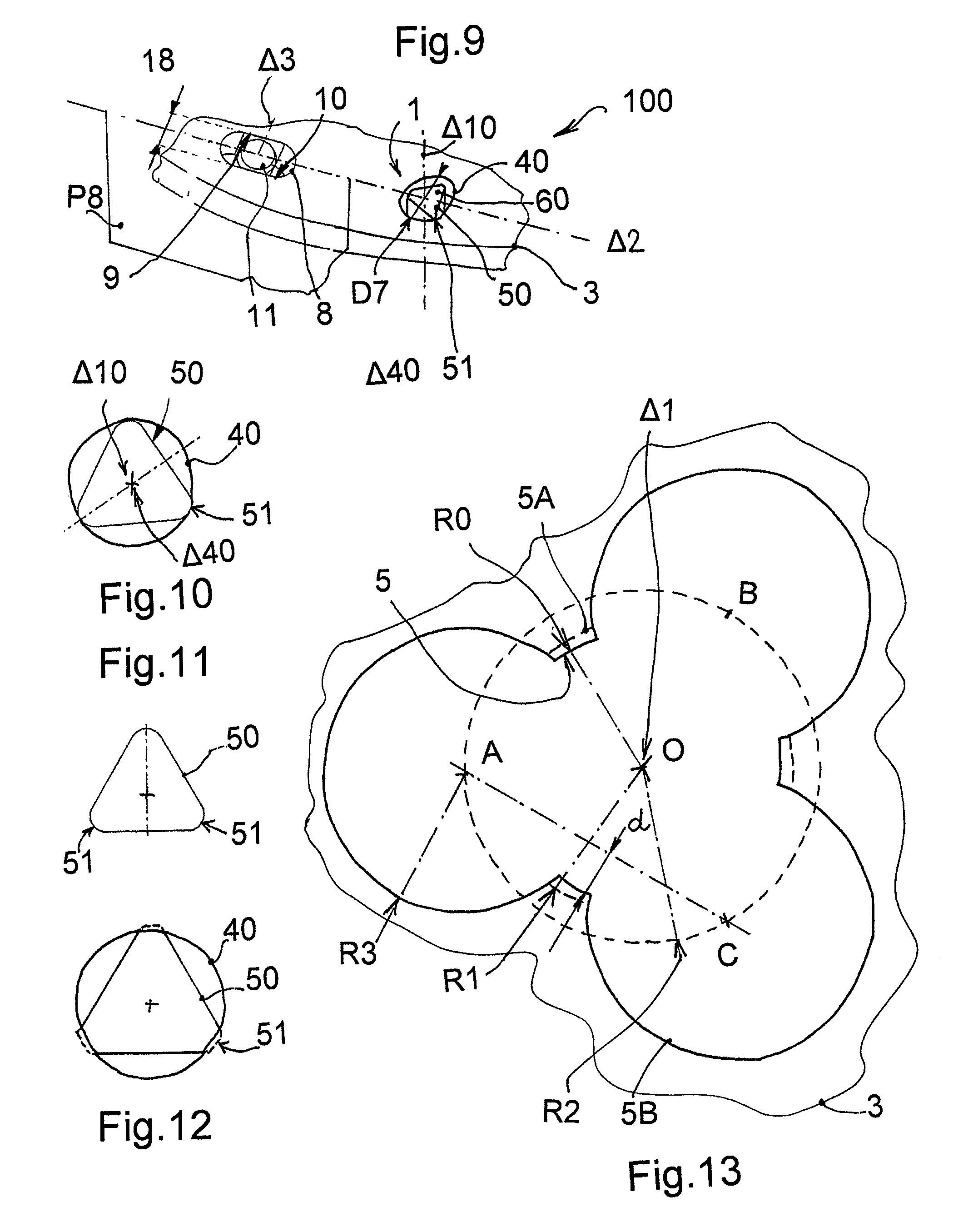
[0091]In the second embodiment shown to FIGS. 9, 10, 12 and 15, when the plate includes a ribbed centring pin 60 with male areas of support 51, the centring housing is realised as a smooth female centring arrangement 40 with revolution symmetry about an axis of revolution Δ40, and said female arrangement 4 is arranged to receive said ribbed centring pin 60 fixed to said bridge 2 and abutting on at least three of said male areas of support 51.

[0092]FIGS. 10 and 11 show a centring device according to the second embodiment with setting between a boring 40 and male cylindrical bearings 51 of the centring pin. FIG. 12 shows a variant where the centring pin is driven clamped in the centring housing 40.

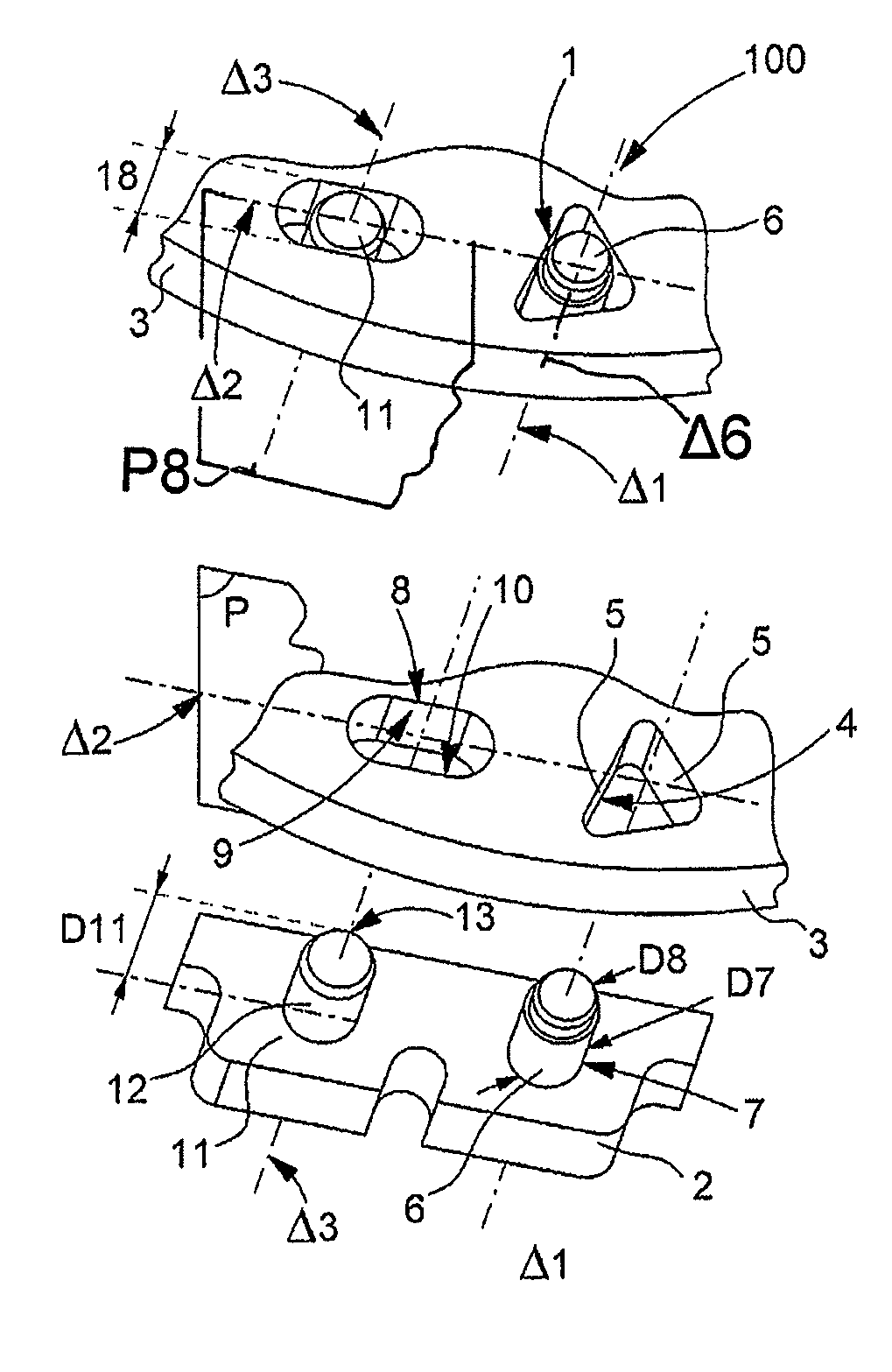
[0093]According to the invention, the centring and alignment device 100 further includes, in the plate 3, for aligning bridge 2 relative to plate 3, an alignment housing 8. This alignment housing 8 is arranged to receive the alignment pin 11 fixed on the bridge 2. The previous remarks concer...

first embodiment

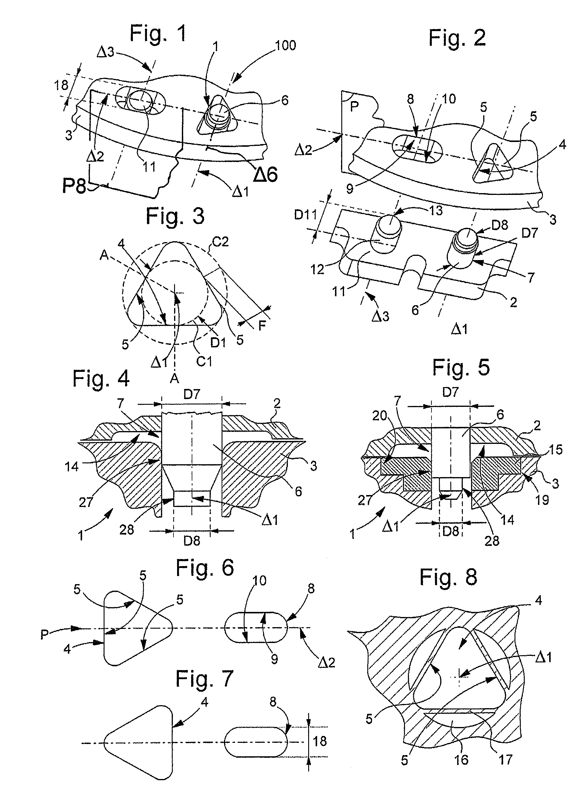
[0099]The alignment housing 8 may still advantageously in the first embodiment, when the bridge 2 carries a smooth centring pin 6, be aligned with a plane of symmetry P of female arrangement 4 with faces parallel to linear axis Δ1.

[0100]For the simplification of the description it is here only described the configuration where the alignment pin 11 is carried cohesive by the bridge 2 and where the alignment housing 8 is installed in the plate 3, but it is naturally possible to substitute a male alignment pin to the female alignment housing and vice versa.

[0101]The distribution of the points of contact between said female arrangement and said pin is preferably regular relative to the circumference of said pin, so as to balance the reaction forces to which said pin is subjected by said female arrangement, relative to the axis of revolution of said pin.

[0102]Preferably the distribution of the contact points between the ribbed female arrangement 4 and the smooth pin 6, and between the sm...


PUM

PropertyMeasurementUnit
diametersaaaaaaaaaa
diametersaaaaaaaaaa
diameteraaaaaaaaaa

Abstract

Positioning device (1) between a bridge (2) and a plate (3). This plate (3) includes: for centering this bridge (2), a female arrangement (4) with faces (5) receiving a cylindrical smooth centering pin (6), fixed to this bridge (2) and abutting on these faces, for aligning this bridge (2) on this plate (3), an alignment housing (8) with parallel faces (9, 10) aligned on this female arrangement (4), receiving an alignment pin (11), fixed to this bridge (2). Collet (15) arranged to be fixed to a plate and including this female centering arrangement (4). Timepiece including a device (1) or collet (15) of this type. Method of assembling this bridge (2) on this plate (3) with this device (1).

Description

[0001]This application claims priority from European Patent Application No. 10192498.3 filed Nov. 25, 2010, the entire disclosure of which is incorporated herein by reference.FIELD OF THE INVENTION[0002]The invention concerns a positioning device between a bridge and a plate. The invention particularly concerns a centring and alignment device between a bridge and a plate for horology. The invention still concerns a centring device.[0003]The invention also concerns a collet, arranged to be fixed to a plate and including a centring housing for centring a pin on said plate.[0004]The invention also concerns a timepiece incorporating at least one such device or at least one such collet.[0005]The invention also concerns a method of mounting a bridge on a plate using this type of device.[0006]The invention concerns the field of micro-mechanics and more specifically the field of horology.BACKGROUND OF THE INVENTION[0007]The technical problem is that of precisely mounting a component hereina...

Claims


Application Information

Patent Timeline
Patent Type & Authority Patents(United States)
IPC IPC(8): G04B19/00
CPCG04B29/04Y10T29/49579Y10T29/53022
Inventor WYSSBROD, BAPTIST
Owner ETA SA MFG HORLOGERE SUISSE
Why Eureka
Try Eureka