Pinch valve

a technology of pinch valve and valve body, which is applied in the direction of diaphragm valve, valve details, valve arrangement, etc., can solve the problem of blocking the flow of fluid through the interior of the condui

Active Publication Date: 2014-01-07
SMC CORP
View PDF18 Cites 43 Cited by
  • Summary
  • Abstract
  • Description
  • Claims
  • Application Information

AI Technical Summary

Benefits of technology

[0006]However, with the aforementioned pinch valve, there is a demand for further miniaturization thereof, as well as for enabling switching of the flow state of the fluid to be accomplished more rapidly.
[0007]A general object of the present invention is to provide a pinch valve which can be made lighter in weight and smaller in scale, while also being capable of more rapidly switching the flow state of a fluid.
[0008]The present invention is characterized by a pinch valve comprising a body, an elastic conduit supported in the body and through which a fluid flows, a solenoid connected to the body and having a coil, the solenoid being excited by energizing the coil for attracting a movable iron core toward a fixed iron core, a valve mechanism having a valve plug disposed to face toward the conduit and which is displaceable along an axial direction of the body, wherein the valve mechanism presses the valve plug toward the conduit by excitation of the solenoid, and an elastic means that urges the movable iron core toward the fixed iron core. By displacement of the valve plug toward the conduit, the conduit is clamped between the valve plug and the body, to thereby interrupt flow of the fluid.
[0009]According to the present invention, in the solenoid, the coil is energized by supplying electrical power thereto, so that the movable iron core is attracted to the side of the fixed iron core, and the elastic means is disposed in the solenoid, which biases the movable iron core toward the fixed iron core. In addition, when the movable iron core is attracted to the side of the fixed iron core upon excitation of the solenoid, and the valve plug is displaced toward the conduit through the movable iron core for pressing the conduit, in the movable iron core, because the elastic force of the elastic means is added together with the attractive force of the solenoid, a reactive force of the elastic conduit is overcome, so that the conduit can be deformed and flow of the fluid can be interrupted.
[0010]Consequently, with a simple structure including the elastic means, because a large pressing force can be secured for pressing the conduit by the valve plug, for example, compared to a case of a pressing force of the same degree but without providing a spring therein, the solenoid can be made lightweight and smaller in size. Further, when the valve plug is operated through the movable iron core, by adding thereto the elastic force of the elastic means, the valve plug can be moved more rapidly toward the conduit.

Problems solved by technology

In addition, for example, by pressing and moving the piston toward the conduit under a supply action of a pressure fluid, the piston is moved together with the clamping piece, whereby the conduit is clamped and crushed between the body and the clamping piece, and as a result, flow of the fluid through the interior of the conduit is blocked.

Method used


Image

  • Pinch valve
  • Pinch valve
  • Pinch valve

Examples


first embodiment

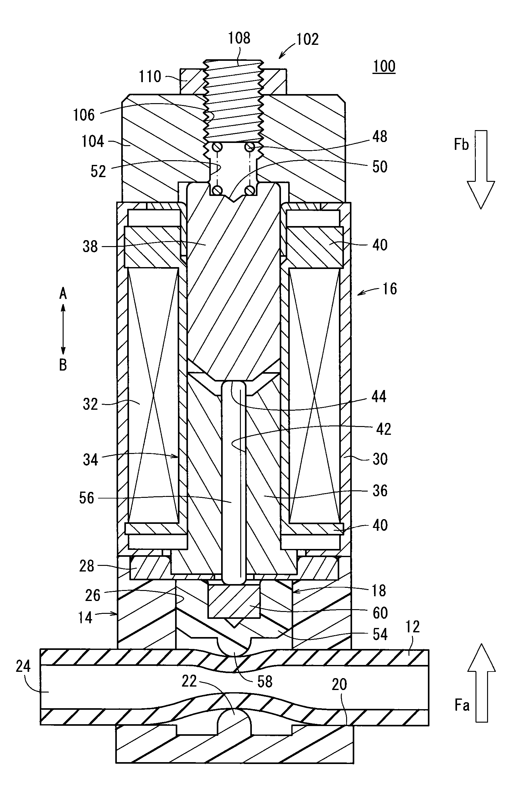
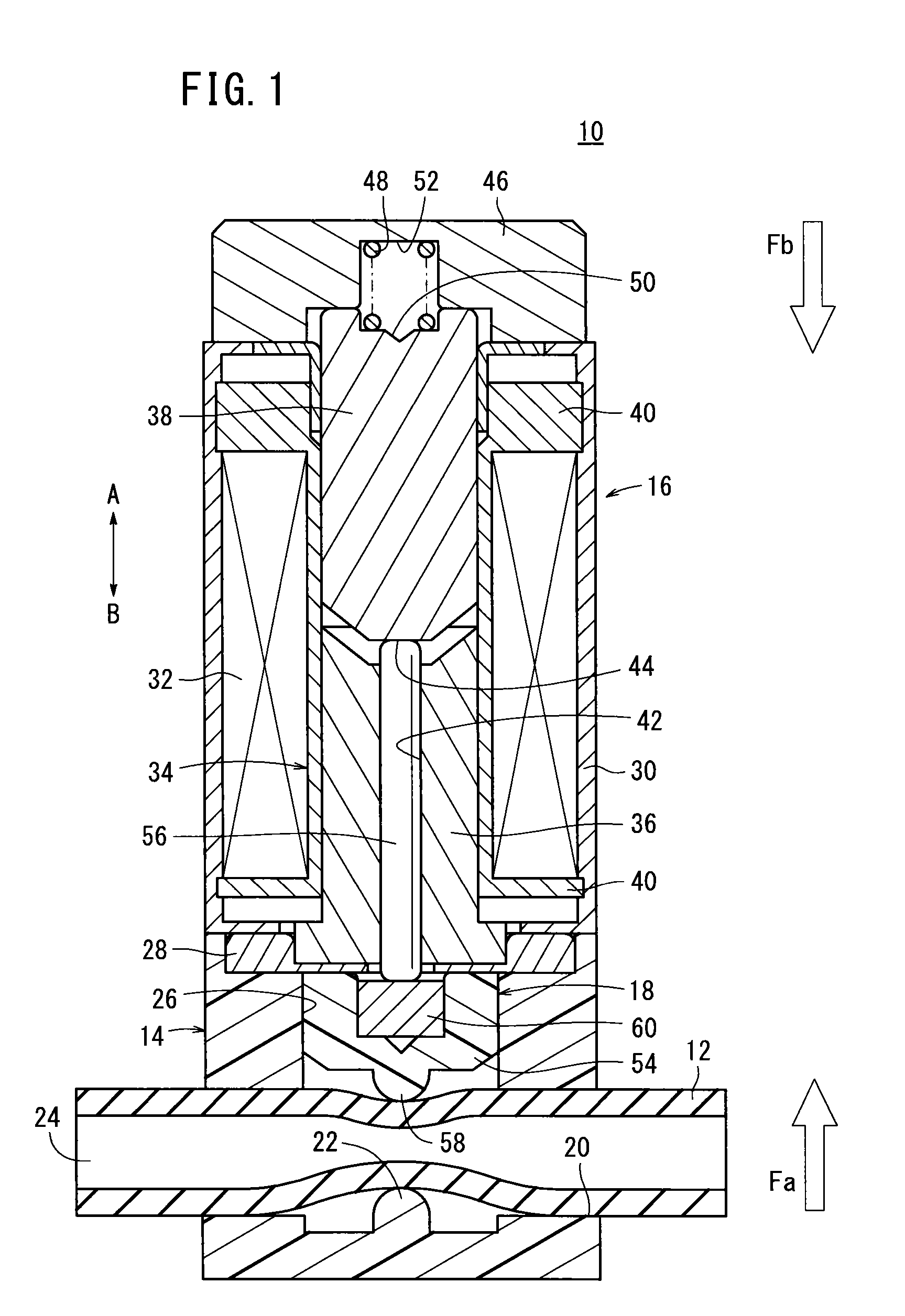
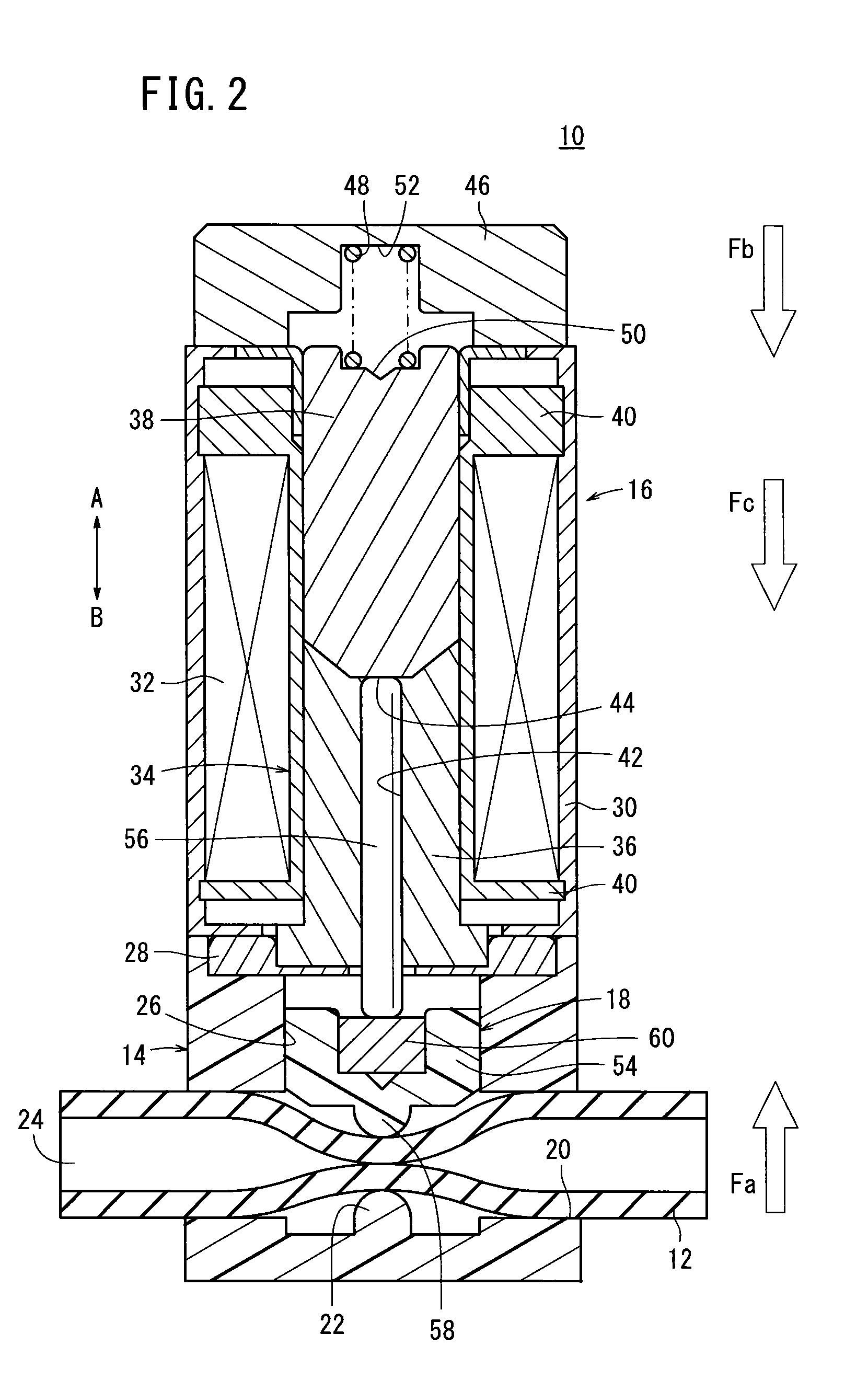
[0016]In FIG. 1, reference numeral 10 indicates a pinch valve according to the present invention.

[0017]As shown in FIGS. 1 and 2, the pinch valve 10 includes a body 14 having a tube (conduit) 12 inserted therein through which a fluid, for example, water or blood, flows, a solenoid 16 connected to an upper part of the body 14, and a valve mechanism 18 provided in the interior of the solenoid 16 and the body 14, which is displaceable along an axial direction (the direction of arrows A and B) upon excitation of the solenoid 16.

[0018]The body 14 is formed, for example, from a resin material having a through hole 20 that penetrates linearly therethrough, with a clamping member 22 that projects upwardly (in the direction of the arrow A) being formed substantially in the center thereof. The clamping member 22 is arranged perpendicularly with respect to the direction of extension of the through hole 20, and is formed to project at a given height with respect to the inner circumferential sur...

second embodiment

[0050]In the foregoing manner, for example, even in the case that the tube 12 is replaced by another tube formed from a material having a different elasticity, and the reactive force Fa of the tube 12 changes, since the elastic force imposed on the movable iron core 38 from the spring 48 can be adjusted by the adjustment mechanism 102 responsive to the reactive force Fa, an advantage exists in that it is unnecessary to exchange the spring 48 with another one having a different elastic force, each time that the tube 12 is replaced.

[0051]More specifically, in the case that the reactive force Fa of the tube 12 becomes greater as a result of replacing or exchanging the tube 12, by moving the adjustment bolt 108 toward the side of the tube 12 (in the direction of the arrow B), the spring 48 is compressed, and the elastic force Fb of the spring 48 increases. Conversely, in the event that the reactive force Fa of the tube 12 is decreased, by moving the adjustment bolt 108 in a direction a...


PUM


Abstract

A pinch valve includes a spring disposed between a movable iron core of a solenoid and an end cover thereof, and which urges the movable iron core toward the side of a tube provided in a body. An elastic force of the spring is set to be smaller than a reactive force of the tube that is applied to a valve plug. In a non-excited state of the solenoid, the valve plug is pressed toward the solenoid by the reactive force of the tube, so as to enable a fluid to flow through a flow passage of the tube. Conversely, in an excited state of the solenoid, since an attractive force of the movable iron core toward the tube is added to the elastic force of the spring, the valve plug is pressed in opposition to the reactive force of the tube for thereby blocking the flow passage.

Description

CROSS-REFERENCE TO RELATED APPLICATION[0001]This application is based upon and claims the benefit of priority from Japanese Patent Application No. 2011-246411 filed on Nov. 10, 2011, of which the contents are incorporated herein by reference.BACKGROUND OF THE INVENTION[0002]1. Field of the Invention[0003]The present invention relates to a pinch valve, which is capable of switching the flow state of a fluid that flows through a passage.[0004]2. Description of the Related Art[0005]Heretofore, a pinch valve has been used for switching the flow state of a fluid that flows inside a conduit made up of a tube or the like. As disclosed, for example, in Japanese Laid-Open Patent Publication No. 2002-174352, such a pinch valve is equipped with a body, a conduit provided in the body through which a fluid flows, a clamping piece for deforming the conduit by clamping the same and thereby switching the flow state of the fluid, and a piston for urging the clamping piece in directions to approach a...

Claims


Application Information

Patent Timeline
Patent Type & Authority Patents(United States)
IPC IPC(8): F16K7/04F16K31/02
CPCF16K31/06F16K7/045F16K7/04F16K7/06
Inventor FUKANO, YOSHIHIROMAKADO, SHOICHIUSHIJIMA, YASUHIRO
Owner SMC CORP
Why Eureka
Try Eureka