Flow control device

Active Publication Date: 2014-01-21
HARTMANN
View PDF11 Cites 1 Cited by
  • Summary
  • Abstract
  • Description
  • Claims
  • Application Information

AI Technical Summary

Benefits of technology

[0003]It is common for draught beer to be supplied from pressurized kegs to the taps at a bar using a pressurized gas. In this way, the pressurized gas effectively pushes the beer from the keg to the tap, through the supply line. However, as a keg empties and there is only a small amount of liquid left in the keg, the pressurized gas is known to create a foam from the remaining liquid. This foam then enters the supply line and will eventually reach the taps. This is undesirable as the foam or froth cannot be served to customers and must therefore be discarded, resulting in wastage and a decrease in profitability. Additionally, all the foam must be drained from the supply line when a new, full keg is fitted, thereby resulting in more wastage and also a delay in serving customers. Finally, the presence of foam in the supply lines can reduce the overall hygiene of the system.
[0017]In a further embodiment of the invention there is provided a flow control device in which the vent valve is rotatably mounted in the top section. In this way, the vent valve may be rotated as necessary to facilitate the installation of a suitable vent line thereto.

Problems solved by technology

Additionally, there remains space surrounding the float valve through which the beer may flow.

Method used


Image

  • Flow control device
  • Flow control device
  • Flow control device

Examples


Embodiment Construction

[0018]The invention will now be more clearly understood from the following description of an embodiment thereof given by way of example only with reference to the accompanying drawings in which:—

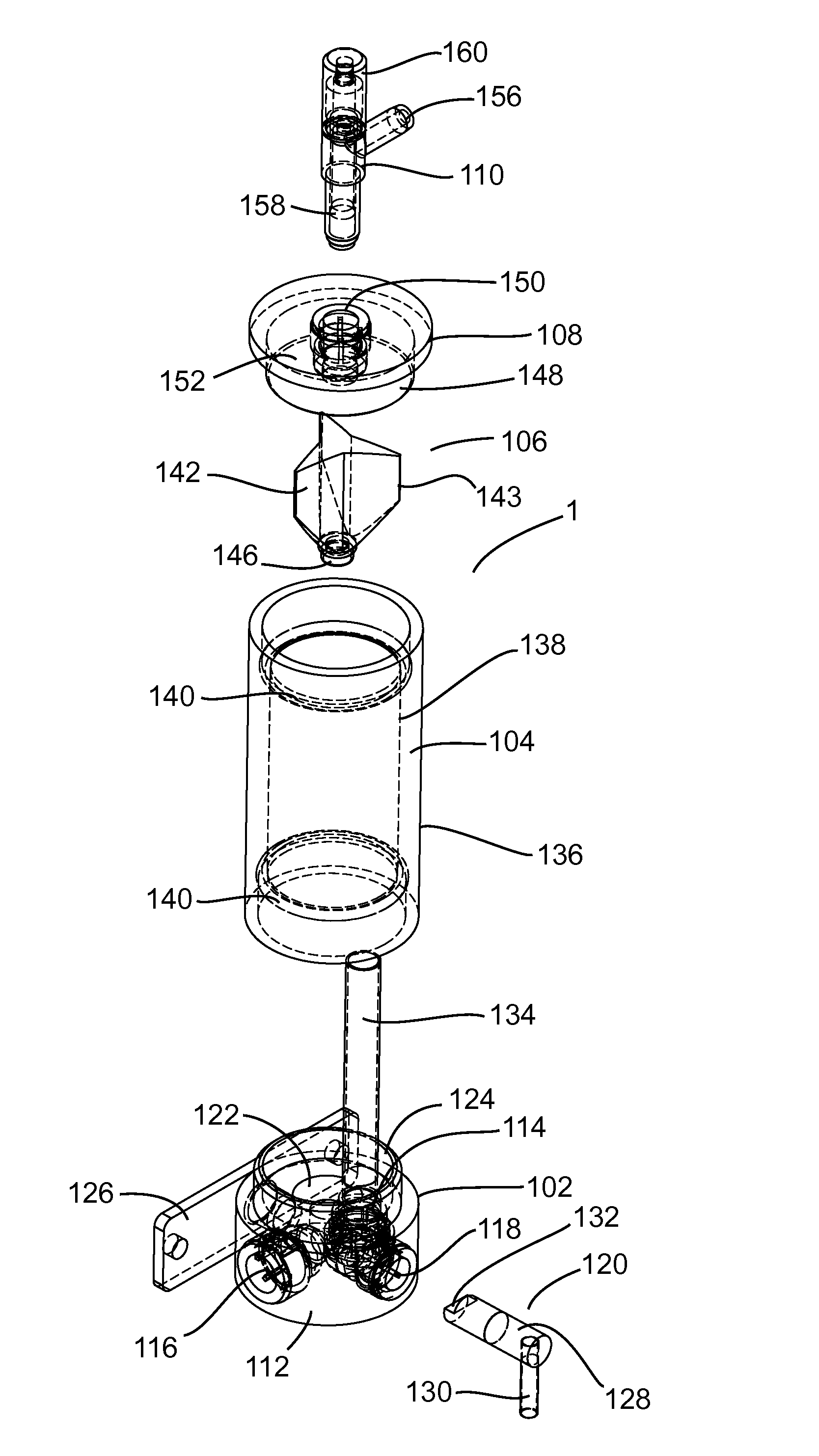
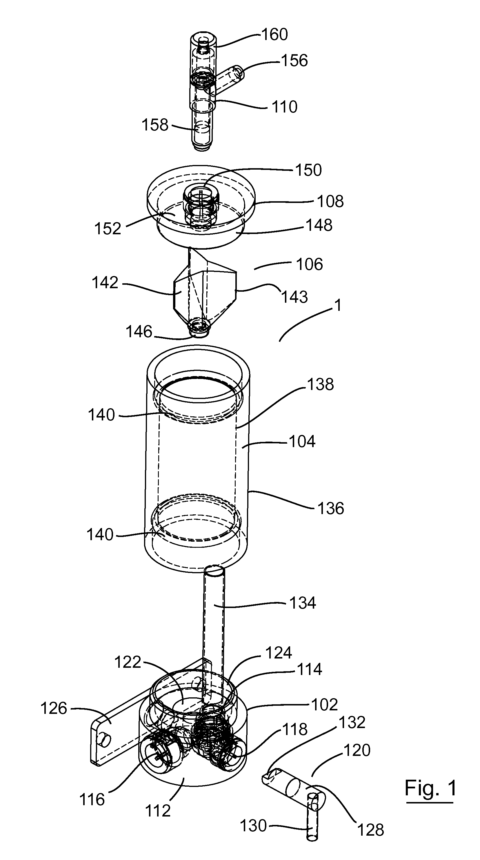
[0019]FIG. 1 is an exploded view of the device according to the invention;

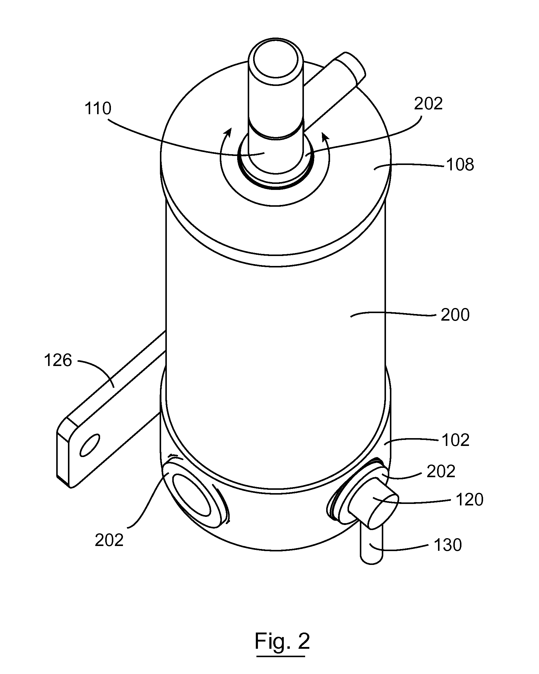
[0020]FIG. 2 is a perspective view of the device according to the invention;

[0021]FIGS. 3(a), (b) and (c) are side, perspective and top views, respectively, of the float valve;

[0022]FIG. 4 is a detail cross-section view of a portion of the device showing the inlet and outlet;

[0023]FIG. 5 is a detail cross-section view of a portion of the device, including the vent valve; and

[0024]FIG. 6 a detail cross-section view of a portion of the device showing the float lifter

[0025]Referring to the drawings, and initially to FIG. 1 thereof, there is shown a flow control device indicated generally by the reference numeral 1, comprising a substantially cylindrical base section 102, a substantially cylindrical tube forming a wall 104...


PUM


Abstract

A flow control device for use in a supply line between a pressurized liquid container and a dispenser for the liquid, the flow control device comprising a chamber (200) having an inlet (114) for receiving liquid from the container; a base section (102) comprising a chamber outlet (122) for supplying liquid to the dispenser; a vent valve (110) for venting gas from the chamber (200); a float valve (106) comprising a float section (142) and a seat section (146) and movable to and from an open position wherein the chamber outlet (122) is open to liquid flow and a closed position wherein the chamber outlet (122) is closed to liquid flow; and a float valve opening mechanism (120) Wherein the float section (142) of the float valve (106) comprises a plurality of protrusions (143), at least some of which engage the inside (138) of the chamber (200) so as to locate the float valve (106) substantially in line with the chamber outlet (122). In this way, the float valve can guide itself into the correct position without the need for additional guiding components.

Description

RELATED APPLICATIONS[0001]The subject application is a U.S. National Stage application of International Application No. PCT / EP2008 / 067472, filed on 12 Dec. 2008, which claims the priority of Irish Patent Application No.: S2007 / 0898, filed on 12 Dec. 2007, the contents of which are herein incorporated by reference in its entirety.INTRODUCTION[0002]The present invention relates to a flow control device for use in a supply line between a pressurized liquid container and a dispenser for the liquid, the flow control device comprising a chamber having an inlet for receiving liquid from the container; a base section comprising a chamber outlet for supplying liquid to the dispenser; a vent valve for venting gas from the chamber; a float valve comprising a float section and a seat section and movable to and from an open position wherein the chamber outlet is open to liquid flow and a closed position wherein the chamber outlet is closed to liquid flow; and a float valve opening mechanism.[000...

Claims


Application Information

Patent Timeline
Patent Type & Authority Patents(United States)
IPC IPC(8): F16T1/20F16K31/18
CPCB67D1/1272B67D1/1247Y10T137/7426Y10T137/2987Y10T137/3068
Inventor HARTMANN, FRANK
Owner HARTMANN
Why Eureka
Try Eureka