

Method for operating a fired furnace and arrangement comprising such a furnace
a technology of firing furnace and furnace, which is applied in the direction of furnaces, lighting and heating apparatus, manufacturing tools, etc., can solve the problems of wasting heat released into the environment by the flue gas escaping from the regenerator, comparatively inefficient heat recovery from the flue gas in the known process of operating glass melting furnaces
- Summary
- Abstract
- Description
- Claims
- Application Information
AI Technical Summary
Benefits of technology
Problems solved by technology
Method used
Image

Examples
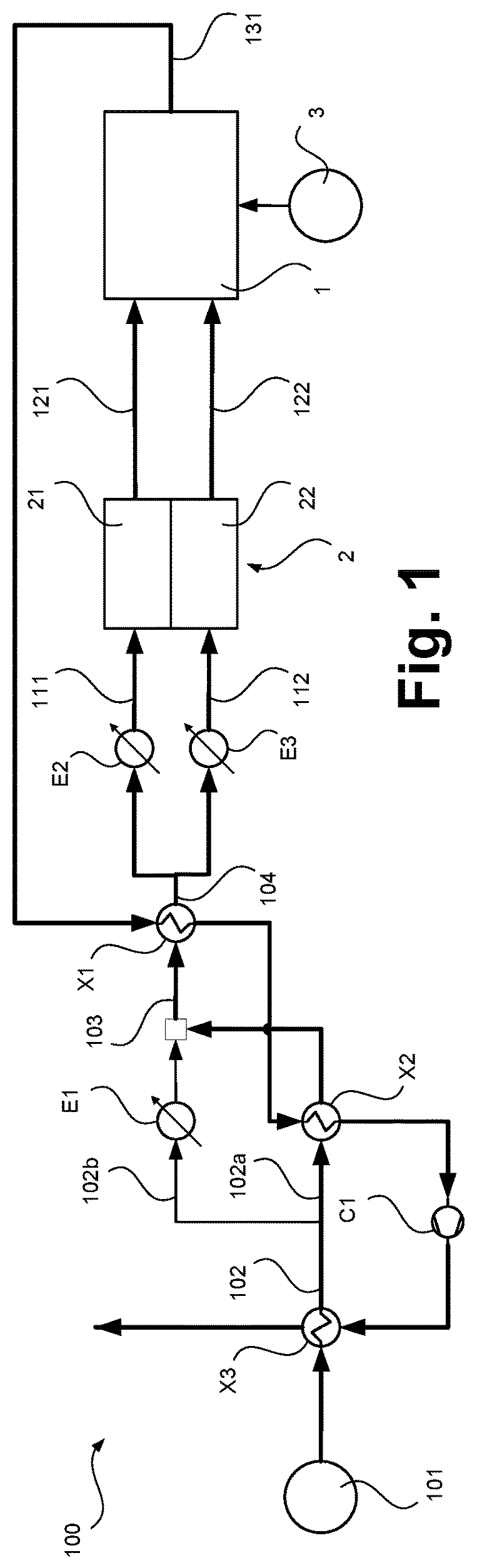
first embodiment
[0044]The preheating of the water used to generate the saturated steam takes place in the present invention, but also in all other forms, in a third heat exchange step before, which is explained below, and in which the combustion product stream is further cooled and in particular (partially) condensed.
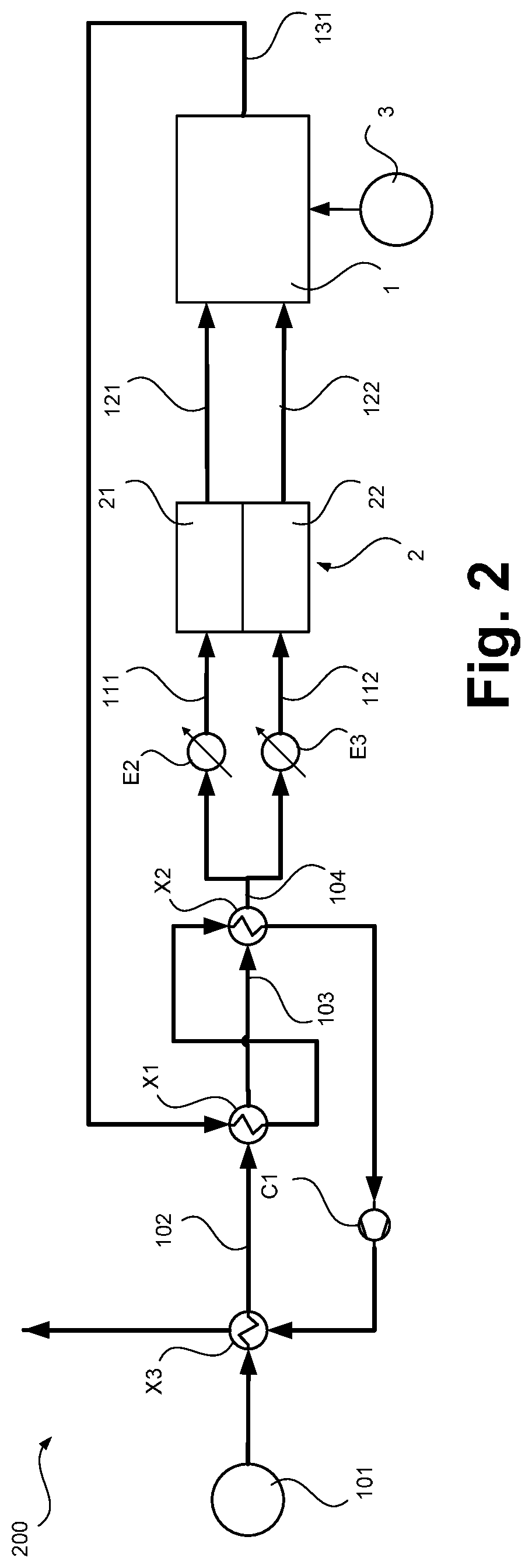
[0045]In a second embodiment of the present invention that is alternative to the first embodiment, the combustion product stream is first used for evaporation and only then for superheating the steam. Again, however, the corresponding heat exchange steps are given below from the direction of the combustion product stream from higher to lower temperature.
[0046]The heat exchange steps used in the second embodiment of the invention include a first heat exchange step in which the combustion product stream is cooled from its initial temperature level, as previously explained, and at the pressure previously explained for the first heat exchange step to a temperature level of, for example, ab...
second embodiment
[0047]In this second embodiment of the present invention, the heat exchange steps also include a second heat exchange step in which the combustion product stream or part of it is cooled from a temperature level of, for example, approx. 600 to 700° C. to a temperature level of, for example, approx. 100 to 200° C. The heat exchange steps are then used to cool the combustion product stream or part of it. Cooling can, for example, take place from the mentioned temperature level of approx. 620° C. to a temperature level of approx. 150° C., wherein here too the pressure level can be lowered from atmospheric pressure to slightly below atmospheric pressure.
[0048]In contrast to this second heat exchange step, in the second embodiment of the invention the saturated steam generated in the first heat exchange step is superheated from a temperature level of, for example, approx. 100 to 120° C. to a temperature level of, for example, approx. 600 to 700° C., in particular approx. 590° C., while ob...
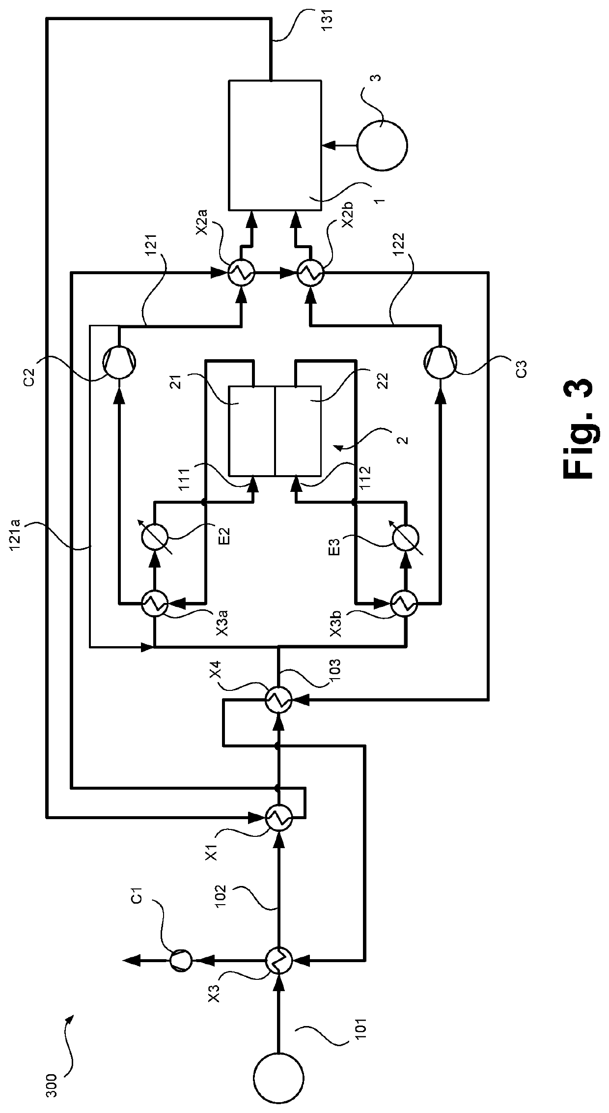
third embodiment
[0050]In the present invention, which differs once again, the heat integration in the second heat exchange step no longer takes place to generate superheated steam, but (at least predominantly) to heat the hydrogen-containing and / or the oxygen-containing substance stream which is formed in the high-temperature electrolysis.
[0051]In this third configuration, the second heat exchange step comprises cooling the combustion product stream or part thereof from a temperature level of, for example, approx. 600 to 700° C., in particular approx. 620° C., to a temperature level of (only), for example, approx. 300 to 400° C., in particular approx. 380° C., and heating, in the second heat exchange step, the hydrogen-containing and / or oxygen-containing substance stream formed in the high-temperature electrolysis. The cooling of the combustion product stream or its part can, for example, take place under slight pressure reduction from atmospheric pressure to approx. 0.95 bar. In a further sub-step...
PUM
| Property | Measurement | Unit |
|---|---|---|
| temperature | aaaaa | aaaaa |
| temperature | aaaaa | aaaaa |
| temperature | aaaaa | aaaaa |
Abstract
Description
Claims
Application Information