Improvements relating to steering assemblies

a technology of steering column and assembly, which is applied in the direction of steering parts, vehicle components, transportation and packaging, etc., can solve the problems of eps collision with some parts, and achieve the effect of low profil

Inactive Publication Date: 2014-01-21
TRW LIMITED
View PDF13 Cites 7 Cited by
  • Summary
  • Abstract
  • Description
  • Claims
  • Application Information

AI Technical Summary

Benefits of technology

[0012]This arrangement enables a steering assembly with a reduced profile to be provided compared with the prior art, making the energy absorbing connection less likely to interfere with any surrounding objects, because the connection no longer needs to be made between the bracket and vehicle body as required in the prior art.
[0013]Preferably, the clamp assembly is fixed relative to the outer tube portion when the clamp assembly is both the clamped and the released condition. Retention of the Inner Column Tube in the Outer Column Tube is then ensured by the provision of the energy absorbing member which prevents the first shroud portion and second shroud portion of the column from sliding apart should the clamping lever be inadvertently moved to the “Unlock” position while the column assembly is being handled or transported inside the car factory.
[0015]This has advantage of providing an especially low profile assembly as the strap can be accommodated within an otherwise unused area of space which would otherwise be occupied by the missing part of the outer tube.
[0016]The energy absorbing member may be located in the slot of the outer tube so that it abuts one edge of the slot. This enables the member to provide an anti-rotation function which involves restraining the Outer Column Tube from rotating slightly when the clamping is released. This matters mainly once the unit is installed in the vehicle. It is an unwanted characteristic of Split-Tube columns that a small rotation of the Outer Column Tube takes place as it unwraps itself from the Inner Column Tube and hence a small but visible rotation of the Column Switch stalks can be seen by the driver. This movement tends to take place in one rotation direction only and the upper column usually returns to its correct position when it is re-clamped. Provided that the energy absorbing member is secured to the Inner Tube precisely so that it contacts with one edge of the split in the Outer Tube this can prevent the said uni-directional rotation associated with releasing the clamp.
[0031]Where the strap is fixed to the inner tube at its end furthest from the steering wheel, a small shape can be formed into the strap such as a hump or a double bend close to the weld. This will provide an amount of lengthwise plastic compliance and minimize tension in the strap that might otherwise arise, due to geometrical effects, as the column collapses in crash.

Problems solved by technology

However there are instances, especially if a column-mounted electrical power assistance system (known as an EPS) is fitted to the lower end of the column, where the area needed to accommodate the above described Energy Strap configuration in the top plate of the Rake Bracket means that the latter will clash with some parts of the EPS before the intended crash stroke can be completed

Method used


Image

  • Improvements relating to steering assemblies
  • Improvements relating to steering assemblies
  • Improvements relating to steering assemblies

Examples


Embodiment Construction

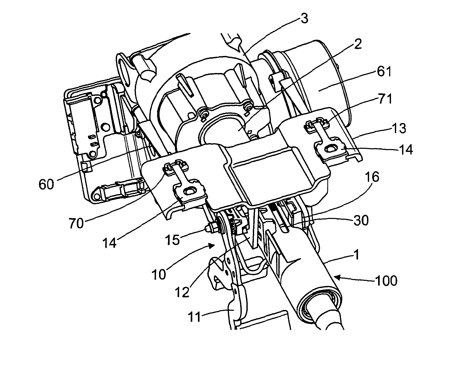
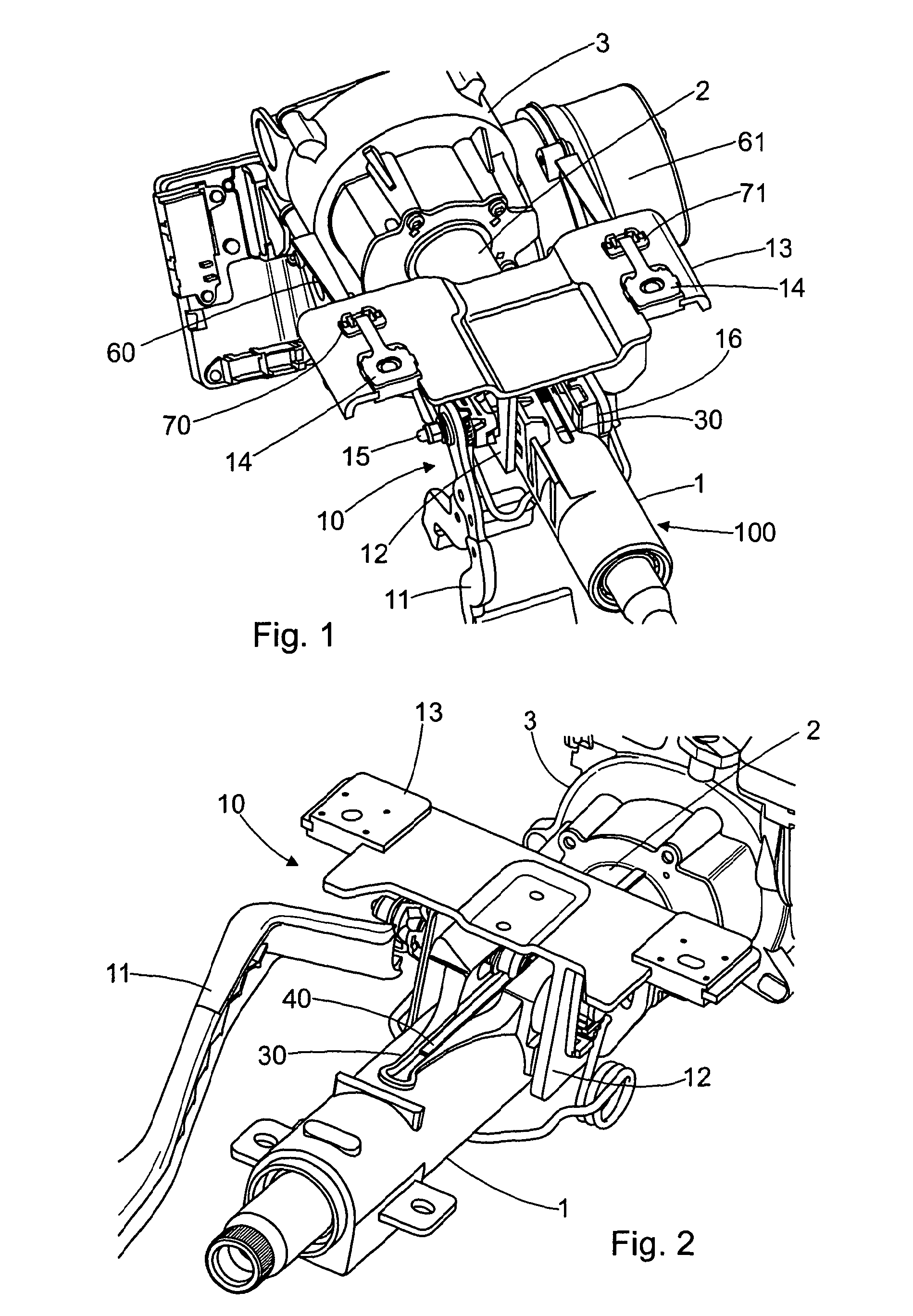
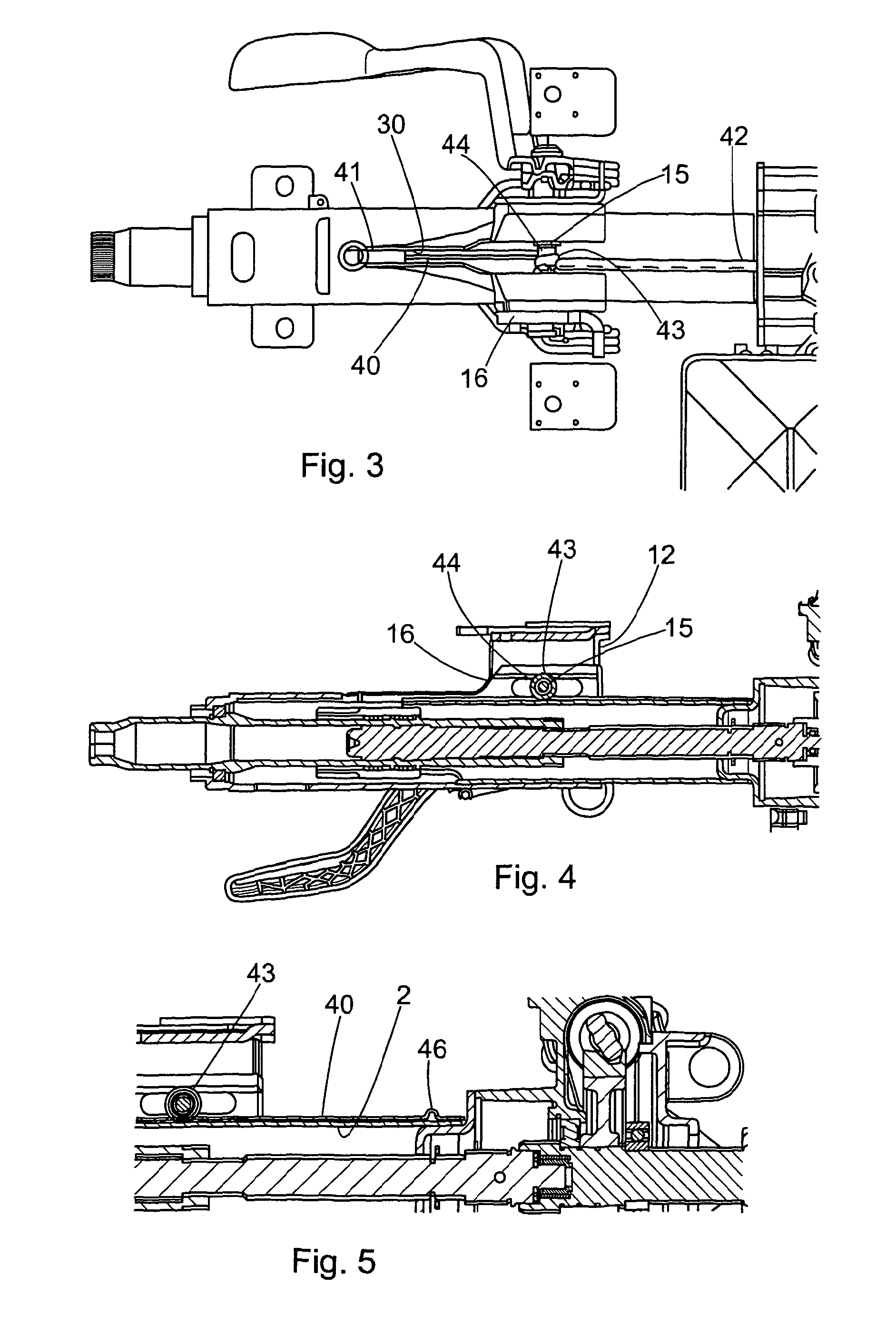
[0061]FIGS. 2 to 15 of the accompanying drawings show various embodiments of the invention applied to a so-called double-adjustment type steering column assembly 100, 200, 300. Such columns can be adjusted for both reach (in and out) and rake angle (up and down). The invention could, equally, apply to single adjust columns and non-adjust columns. The column assembly comprises a first shroud portion 1 and a second shroud portion 2 which can telescope relative to one another to allow for reach adjustment and which can both be moved in an arc around a pivot point axis to allow for rake adjustment. The telescoping mechanism allows the adjustment of the Reach position by the driver and also allows the first shroud portion to move forward in a controlled manner in the event of the steering wheel (not shown) being impacted by the driver in a crash.

[0062]The first shroud portion 1, being closest to the steering wheel, comprises an outer tube which supports the steering wheel shaft 1 via a b...


PUM


Abstract

An adjustable steering column assembly includes a first shroud portion comprising an outer tube, a second shroud portion which comprises an inner tube, and a clamp mechanism that includes a part that is fixed relative to the outer tube, the first and second shroud portions being releasably engaged by the clamp mechanism to selectively permit an amount of relative movement between the first and second shroud portions that is required during adjustment of the steering column assembly, the assembly further including an energy absorbing member which includes a strap that interconnects the inner tube and the part of the clamp bolt assembly, the assembly being so arranged that upon collapse the inner tube moves relative to the clamp assembly whereupon the energy absorbing member is deformed beyond its elastic limit, thereby absorbing energy in the system to control the collapse of the assembly.

Description

CROSS-REFERENCE TO RELATED APPLICATIONS[0001]This application is a national stage of International Application No. PCT / GB2010 / 052034 filed Dec. 6, 2010, the disclosures of which are incorporated herein by reference in entirety, and which claimed priority to Great Britain Patent Application No. GB 0921713.4 filed Dec. 11, 2009 and Great Britain Patent Application No. GB 1008802.9 filed May 26, 2010, the disclosures of which are incorporated herein by reference in entirety.BACKGROUND OF THE INVENTION[0002]The invention relates to adjustable steering column assemblies of the kind which include a first shroud portion, a second shroud portion and a clamp mechanism that includes a bracket secured to a fixed part of a vehicle and in which the first and second portions are releasably engaged by the clamp mechanism to selectively permit an amount of relative movement between the first and second portions that is required during adjustment of the steering column assembly.[0003]Steering column...

Claims


Application Information

Patent Timeline
Patent Type & Authority Patents(United States)
IPC IPC(8): B62D1/00
CPCB62D1/184B62D1/195
Inventor DAVIES, NICLASDUFFY, PATRICK ANTHONY
Owner TRW LIMITED
Why Eureka
Try Eureka