Ram air turbine deployment actuator

a technology of actuators and air turbines, applied in the direction of rod connections, rotors, gearings, etc., can solve the problems of high door load, difficult deployment of actuators when only limited electrical power is available in emergency cases, and relatively high load on actuators in deployment scenarios

Active Publication Date: 2014-02-04
HAMILTON SUNDSTRAND CORP
View PDF31 Cites 44 Cited by
  • Summary
  • Abstract
  • Description
  • Claims
  • Application Information

AI Technical Summary

Problems solved by technology

Deploying the actuator when only limited electrical power is available in emergency cases is challenging.
The loads on the actuator in a deployment scenario can become relatively high due to aircraft flight conditions.
These emergency conditions can generate high door loads when attempting to push the RAT into the air stream in-flight.
But, the load that can be applied to the actuator is limited.

Method used


Image

  • Ram air turbine deployment actuator
  • Ram air turbine deployment actuator
  • Ram air turbine deployment actuator

Examples


Embodiment Construction

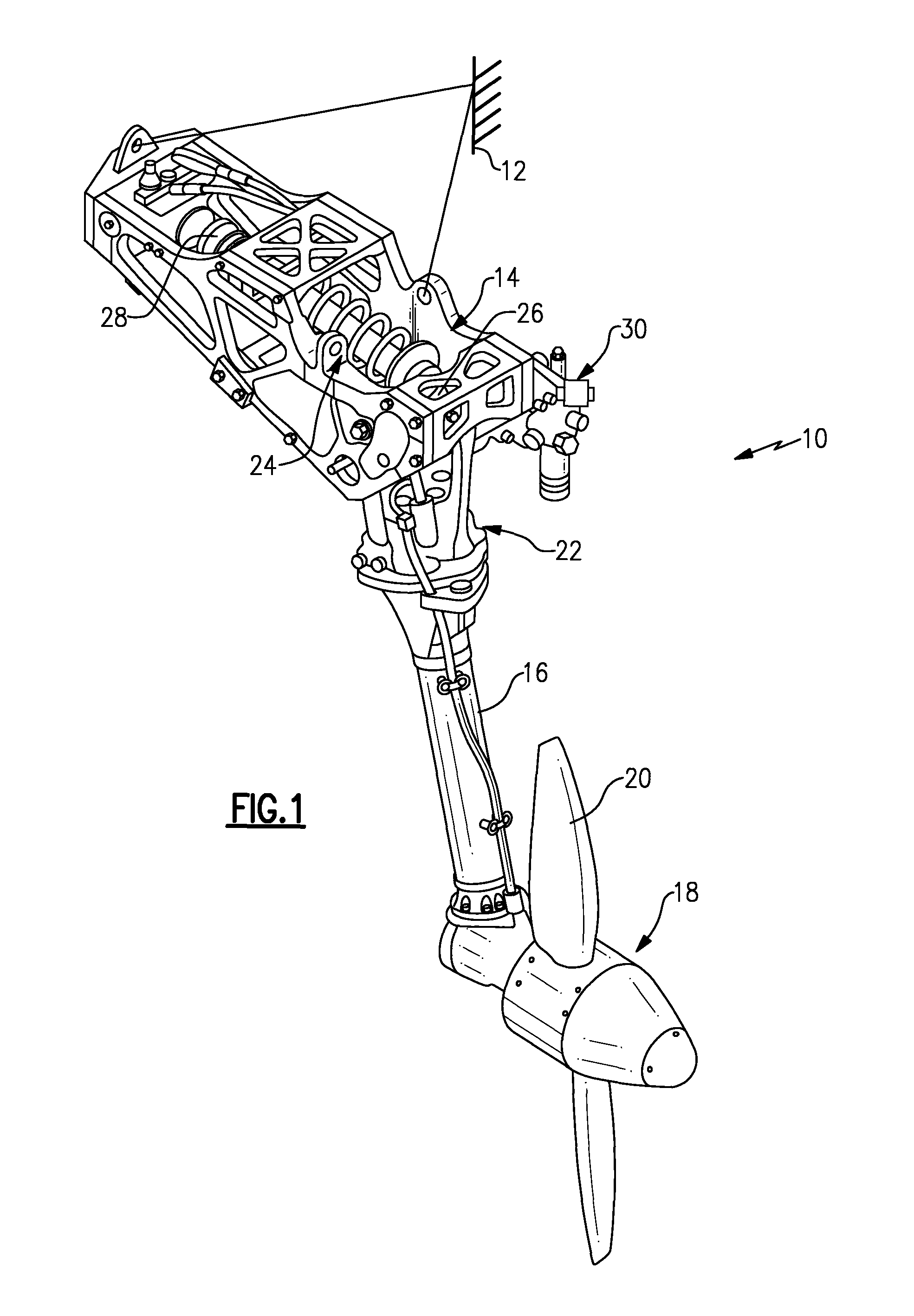
[0016]FIG. 1 illustrates a RAT system 10 secured to an aircraft structure 12 by a housing 14. The housing 14 pivotally supports a strut 16 having a turbine 18 at one end. The turbine 18 includes blades 20, which impart rotational drive to a generator 22 and a hydraulic pump 30. An actuator 24 is secured to the strut 16 at a first end 26 and to the housing at a second end 28. The actuator 24 is illustrated in its deployed position.

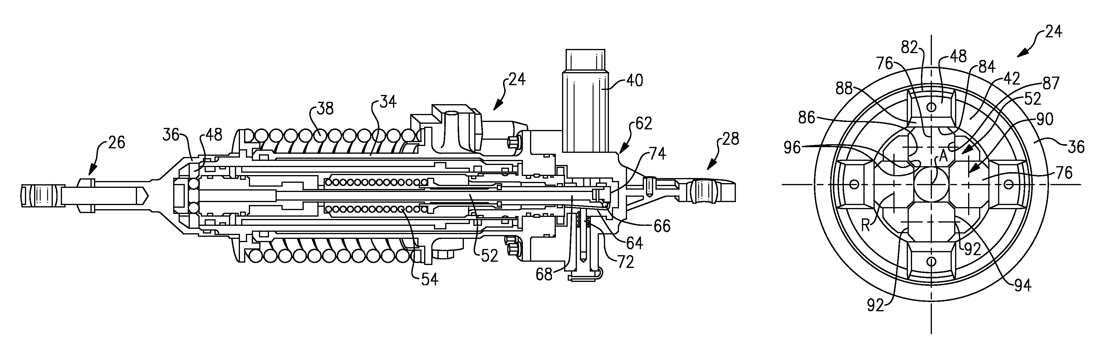
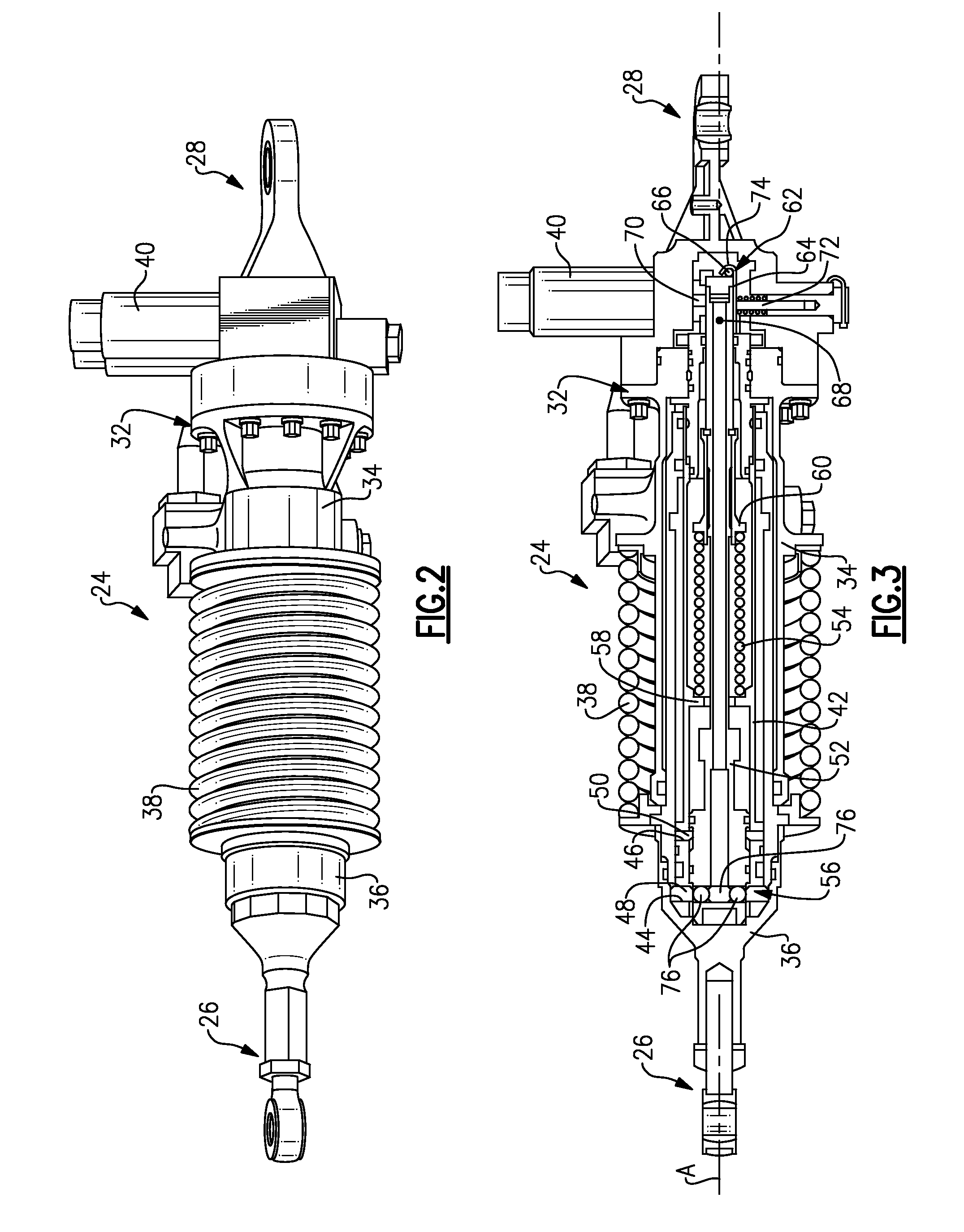
[0017]Referring to FIGS. 2 and 3, the actuator 24 includes a housing 32 having first cylinder 34 and second separate cylinder 36, unattached to housing 32, telescopically arranged relative to one another. A deploy spring 38 is arranged between the first and second cylinders 34, 36 in a compressed state with the actuator 24 in its retracted position. A deploy solenoid 40 is mounted on the housing 32 and is actuated to initiate a deploy sequence within the actuator 24.

[0018]The second cylinder 36 is received within the first cylinder 34. A piston rod 42 is af...


PUM


Abstract

An actuator for a ram air turbine system includes a lock bolt having a multiple circumferentially arranged lateral supports. A piston rod supports multiple up-lock wedges. Multiple rollers are supported by the lateral supports with chamfers on the rollers engaging one another and are configured to radially support the up-lock wedges in a retracted position.

Description

BACKGROUND[0001]This disclosure relates to a ram air turbine (RAT) deployment system, and more particularly, the disclosure relates to an actuator for the system.[0002]Ram Air Turbines (RATs) are utilized on numerous aircraft to provide hydraulic and electrical power in emergency situations. The RAT is stowed in the aircraft structure and deployed into the air stream by a deployment actuator. The deployment actuator is attached to aircraft structure and to an arm on the strut of the RAT. On deployment, the deployment actuator forces the RAT to rotate out of its stowed, or retracted, position in the aircraft and into the air stream. The air stream acts on the RAT blades to spin the turbine and governor assembly, which in turn operates an electrical generator and hydraulic pump providing power to the aircraft. The RAT is held in the aircraft by an up-lock mechanism and is restrained in the deployed position by a down-lock mechanism, both of which are contained within the deployment ac...

Claims


Application Information

Patent Timeline
Patent Type & Authority Patents(United States)
IPC IPC(8): F16H1/24
CPCF05D2270/09F16B7/1409B64D41/007F02C7/32Y10T74/18704Y10T74/18696Y10T74/18888Y10T74/18688B64D41/00F01D7/02F02K7/10
Inventor LANG, DAVID J.SASSCER, GARY
Owner HAMILTON SUNDSTRAND CORP
Why Eureka
Try Eureka