Seismic isolation bearing

a technology of seismic energy and isolation bearing, which is applied in the direction of bearing assembly, rotary machine parts, mechanical equipment, etc., can solve the problems that the isolation bearing cannot dissipate horizontal seismic energy and still destroy the structure, and achieve the effect of increasing the ability to isolate seismic energy

Active Publication Date: 2014-02-04
CHUANG HSUN JEN
View PDF6 Cites 7 Cited by
  • Summary
  • Abstract
  • Description
  • Claims
  • Application Information

AI Technical Summary

Benefits of technology

[0007]The main objective of the present invention is to provide a seismic isolation bearing which employs a shock absorbing pad to increase its ability to isolate seismic energy.
[0008]To achieve the foregoing objective, the seismic isolation bearing in accordance with the present invention comprises a lower plate and an upper plate separated by a slider. The lower plate has an upward facing concave surface. The upper plate has a downward facing concave surface. The slider includes a first member and a second member separated by a shock absorbing pad. The first member has an upper convex surface that slides along the concave surface of the upper plate. The second member has a lower convex surface that slides along the concave surface of the lower plate. In the event of an earthquake, the lower plate and the upper plate are intended to move relative to each other via the slider between the lower and upper plates to dissipate the horizontal seismic energy. In addition, the shock absorbing pad can deform to absorb the vertical seismic energy and to ensure a complete contact between the first member and the upper plate and between the second member and the lower plate. Thus, such seismic isolation bearing employing the shock absorbing pad can increase its ability to isolate seismic energy.

Problems solved by technology

However, such seismic isolation bearing can only dissipate the horizontal seismic energy.
The vertical seismic energy still exists, so that it can still destroy the structure.

Method used


Image

  • Seismic isolation bearing
  • Seismic isolation bearing
  • Seismic isolation bearing

Examples


Embodiment Construction

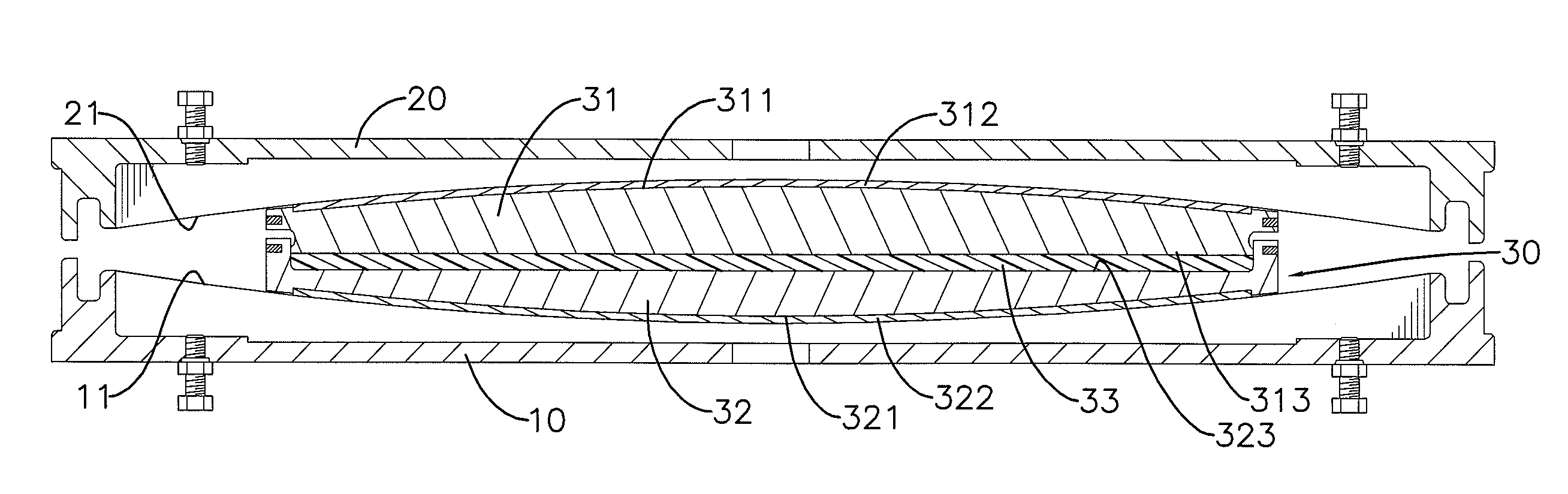
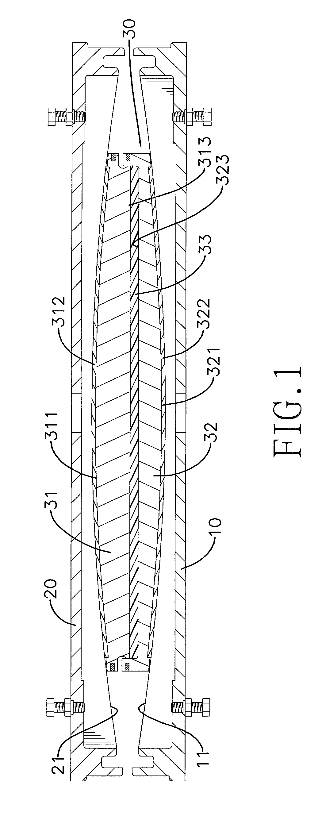
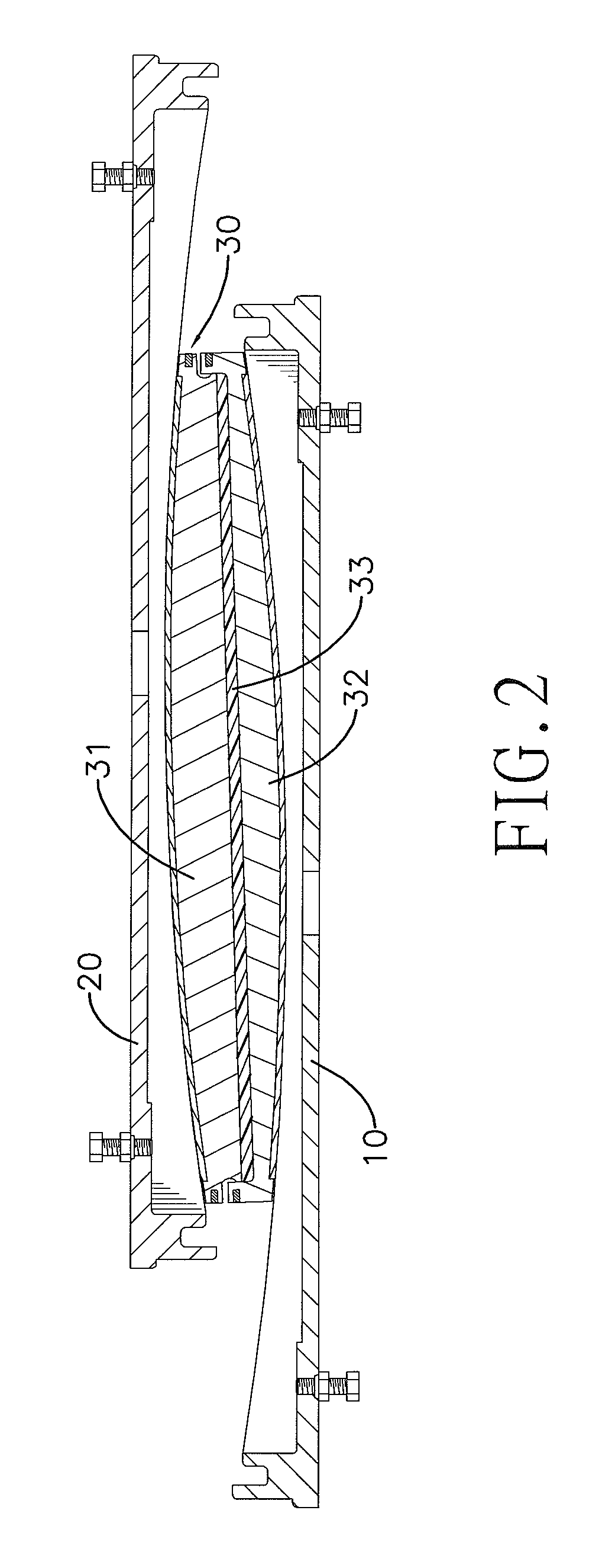
[0014]With reference to FIG. 1, a seismic isolation bearing in accordance with the present invention comprises a lower plate 10, an upper plate 20 and a slider 30.

[0015]The lower plate 10 is a circular steel plate and has an upward facing concave surface 11.

[0016]The upper plate 20 is separated from the lower plate 10, is a circular steel plate and has a downward facing concave surface 21.

[0017]The slider 30 is slidably mounted between the lower and upper plates 10, 20, is circular and includes a first member 31 and a second member 32 separated by a shock absorbing pad 33. The first member 31 has an upper convex surface 311 that slides along the concave surface 21 of the upper plate 20. The second member 32 has a lower convex surface 321 that slides along the concave surface 11 of the lower plate 10. The shock absorbing pad 33 is made of rubber.

[0018]In a preferred embodiment, the first member 31 has a polytetrafluoroethylene (PTFE) piece 312 inlaid in the convex surface 311 thereof...


PUM

PropertyMeasurementUnit
seismic energyaaaaaaaaaa
horizontal seismic energyaaaaaaaaaa
vertical seismic energyaaaaaaaaaa

Abstract

A seismic isolation bearing has a lower plate and an upper plate separated by a slider. The lower plate has an upward facing concave surface. The upper plate has a downward facing concave surface. The slider includes a first member and a second member separated by a shock absorbing pad. The first member has an upper convex surface that slides along the concave surface of the upper plate. The second member has a lower convex surface that slides along the concave surface of the lower plate. In the event of an earthquake, the lower plate and the upper plate are intended to move relative to each other via the slider to dissipate the horizontal seismic energy. In addition, the shock absorbing pad can deform to absorb the vertical seismic energy. Thus, the seismic isolation bearing can increase its ability to isolate seismic energy.

Description

BACKGROUND OF THE INVENTION[0001]1. Field of the Invention[0002]The present invention relates to a seismic isolation bearing and, more particularly, to a seismic isolation bearing which employs a shock absorbing pad to increase its ability to isolate seismic energy.[0003]2. Description of the Prior Arts[0004]A seismic isolation bearing is a base isolation device provided for protecting various structures from the damaging effects of earthquakes. With reference to FIG. 3, a conventional seismic isolation bearing comprises a lower plate 40 and an upper plate 50 separated by a slider 60. The lower plate 40 has an upward facing concave surface 41. The upper plate 50 has a downward facing concave surface 51. The slider 60 has an upper convex surface 61 that slides along the concave surface 51 of the upper plate 50 and has a lower convex surface 62 that slides along the concave surface 41 of the lower plate 40. When in use, the lower plate 40 rests on the ground base on which the structur...

Claims


Application Information

Patent Timeline
Patent Type & Authority Patents(United States)
IPC IPC(8): F16C41/00
CPCF16C29/02F16C29/001F16C2208/32E04H9/021
Inventor CHUANG, HSUN-JEN
Owner CHUANG HSUN JEN
Why Eureka
Try Eureka