Automatic measurement and gain control of distributed Raman amplifiers

a distributed raman amplifier and automatic measurement technology, applied in the direction of lasers, transmission, electromagnetic transmission, etc., can solve the problems of noise, inability to directly measure the changes lack of a direct method of measuring the signal raman gain or the change in the signal raman gain, etc., to achieve the effect of agc mode operation of the amplifier

Active Publication Date: 2014-02-04
II VI DELAWARE INC +1
View PDF16 Cites 19 Cited by
  • Summary
  • Abstract
  • Description
  • Claims
  • Application Information

AI Technical Summary

Problems solved by technology

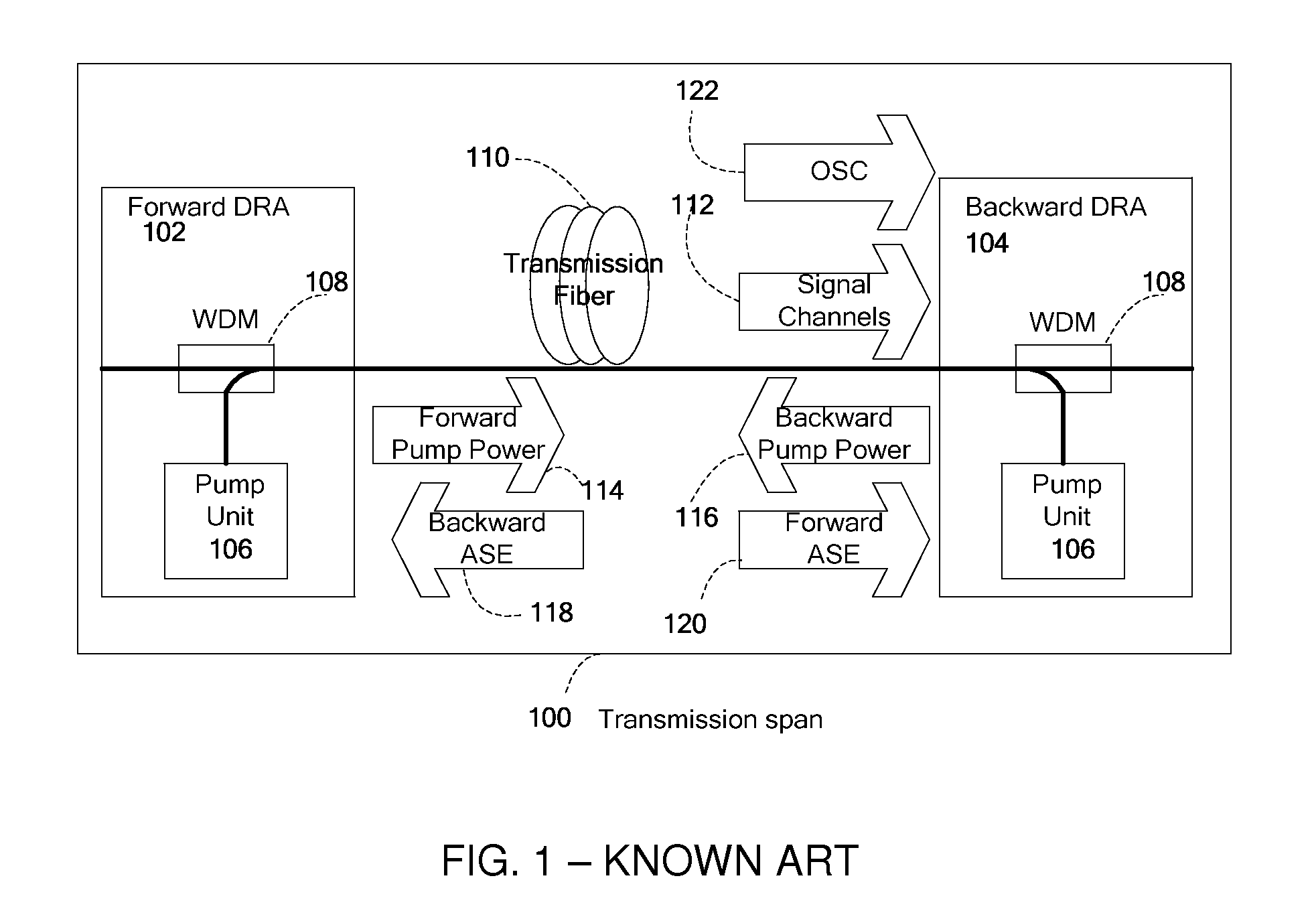
In addition to signal channels amplification, noise is also created due to spontaneous Raman scattering, which is then amplified by the pump power to create amplified spontaneous emission (ASE) noise.
Furthermore, during operation, i.e. when the Raman pumps are operational and a signal is being transmitted, changes in the signal Raman gain cannot be directly measured, since changes in the signal power level can indicate add / drop of a signal channel and / or changes in the transmission line loss and not necessarily changes in the signal Raman gain.
The lack of a direct method of measuring the signal Raman gain or changes in the signal Raman gain severely complicates the operation of the amplifier in AGC mode.
This manual mode of operation is sufficient for relatively small scale DRA deployment, but not for large-scale deployment where DRA is implemented in every span of an optical communications system.

Method used


Image

  • Automatic measurement and gain control of distributed Raman amplifiers
  • Automatic measurement and gain control of distributed Raman amplifiers
  • Automatic measurement and gain control of distributed Raman amplifiers

Examples


Embodiment Construction

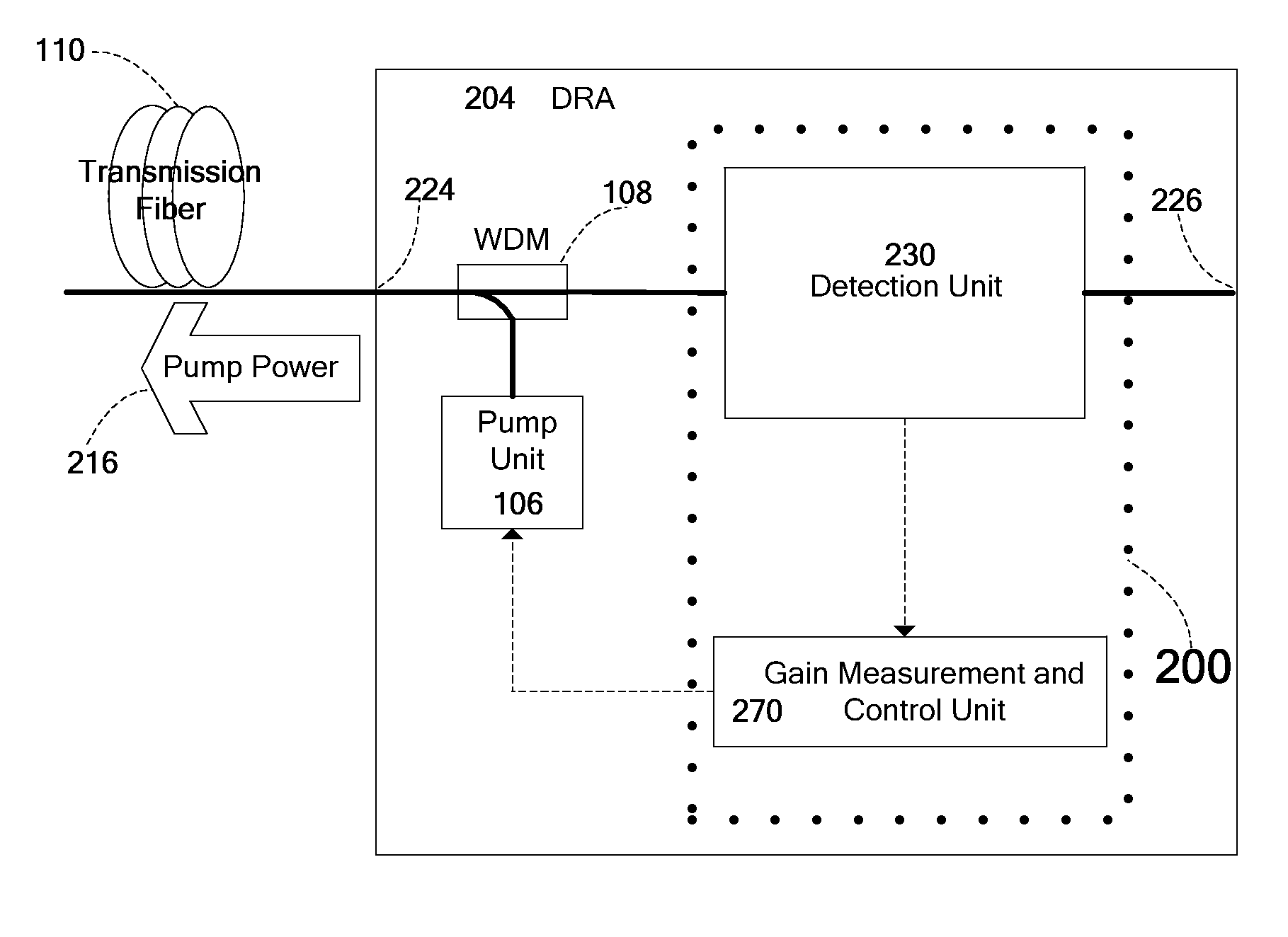
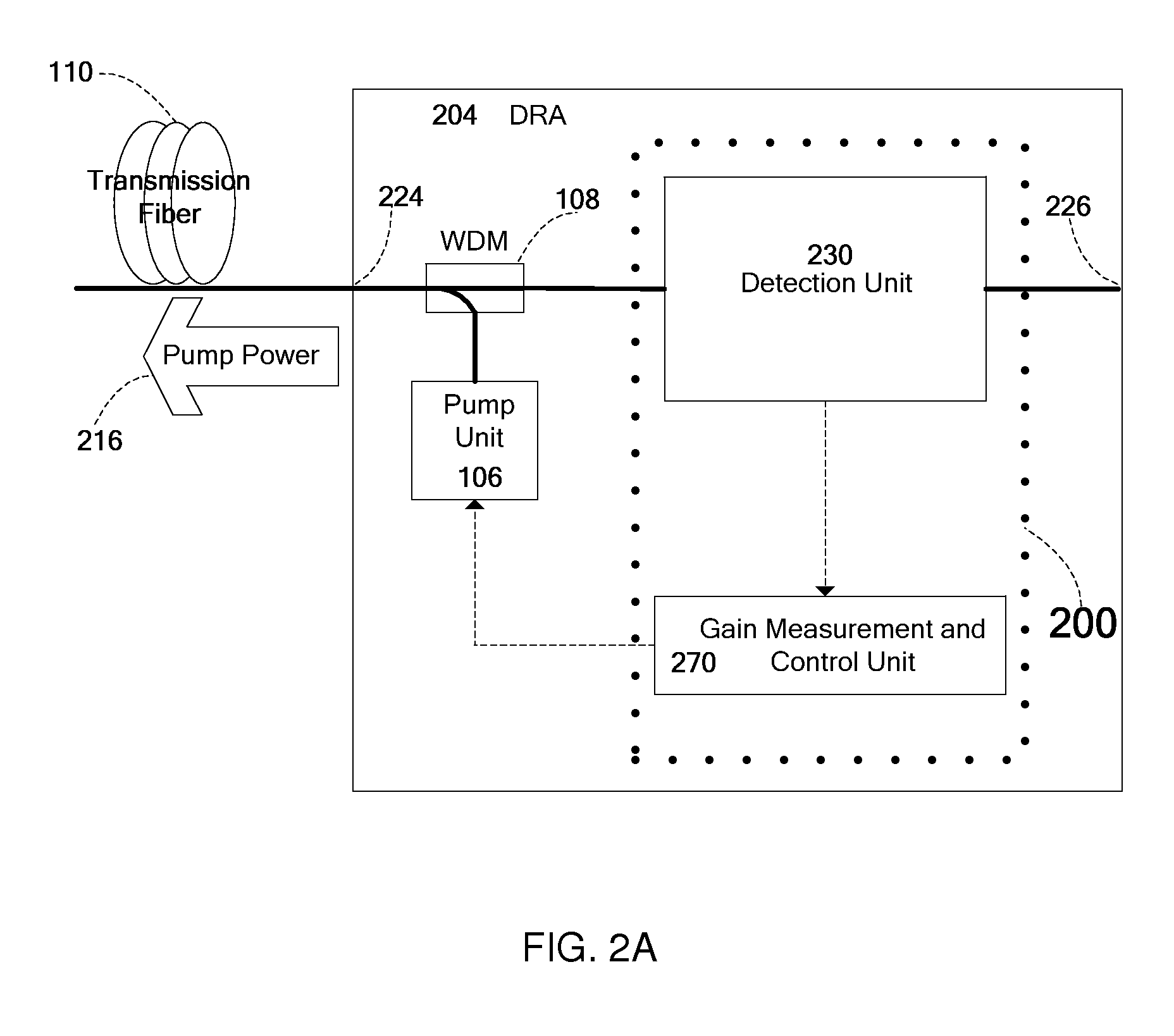
[0029]FIG. 2A shows schematically an apparatus for gain measurement and control in an embodiment of the invention, the apparatus marked as 200. As shown, apparatus 200 is included in a DRA 204 which may be either a forward or a backward DRA. As in known DRAs, DRA 204 includes a pump unit 106 and a WDM 108 to supply pump power 216 to transmission fiber 110. Apparatus 200 includes a detection unit 230 and a gain calculation and control (GCC) unit 270. Note that in some embodiments, apparatus 200 need not be physically located in the same physical enclosure as pump unit 106 and WDM 108. Detection unit 230 is configured to measure both before and during operation of the DRA, the optical power of a filtered component of the light entering DRA 204 via an input port 224 from a transmission fiber 110. As used herein, “during operation” refers to a state in which the Raman pumps are operational and a communication signal is being transmitted along the transmission fiber.

[0030]Detection unit ...


PUM


Abstract

Apparatus and method for gain measurement and control of a Distributed Raman Amplifier (DRA). Various embodiments of the apparatus include a detection unit operative to measure, during operation of the DRA, the optical power of a filtered component of the light entering the DRA from the transmission fiber and a gain calculation and control unit coupled to the detection unit and operative to calculate a signal Raman gain property from the measured optical power. The filtered component may exemplarily be a result of passing the light through a band pass filter, a spectral filter with a given spectral shape or a notch filter. The signal Raman gain property may be an average on-off signal Raman gain, an average net signal Raman gain or a signal Raman gain tilt within a communication band. The apparatus and method may be used to operate the DRA in Automatic Gain Control, i.e. to maintain a required constant signal Raman gain and / or signal Raman gain tilt.

Description

CROSS REFERENCE TO RELATED APPLICATIONS[0001]This application claims priority from U.S. Provisional Patent Application No. 61 / 286,024 titled “Method and system for automatic gain control in distributed Raman amplifiers” and filed 14 Dec. 2009, which is incorporated herein by reference in its entirety.FIELD[0002]Embodiments of the invention relate generally to optical fiber amplifiers used in fiber optics telecommunications systems and more particularly to distributed Raman amplifiers (DRAs).BACKGROUND[0003]A modern optical communication system (also referred to herein simply as “system”) utilizes optical amplifiers to amplify wavelength division multiplexed (WDM) signal channels as they are transmitted through the system. The first optical amplifiers to be commercially deployed were Erbium doped fiber amplifiers (EDFAs), which are self-contained units placed between 60-120 km length spans of a communication link. These units contain a special Erbium doped fiber (EDF) which serves as...

Claims


Application Information

Patent Timeline
Patent Type & Authority Patents(United States)
IPC IPC(8): H01S3/30
CPCH01S3/302H01S3/1301H04B10/2942H01S2301/04H04B10/2916H01S3/0078H01S3/06754H01S2301/02H01S3/13013
Inventor GHERA, URISHLIFER, ALEXBERGER, DANIELZAACKS, MARKMENASHE, DAVID
Owner II VI DELAWARE INC
Why Eureka
Try Eureka