Device for testing performance of optical module

A technology for testing optical and optical modules, applied in electromagnetic wave transmission systems, electrical components, transmission systems, etc., can solve problems such as high testing costs and waste of resources, and achieve the effects of improving testing efficiency, ensuring testing accuracy, and intuitive testing results

Inactive Publication Date: 2018-08-03
四川泰瑞创通讯技术股份有限公司
View PDF8 Cites 19 Cited by
  • Summary
  • Abstract
  • Description
  • Claims
  • Application Information

AI Technical Summary

Problems solved by technology

But this test method and device can be said to be a huge waste of resources for professional instruments, and the test cost will also be high

Method used


Image

  • Device for testing performance of optical module
  • Device for testing performance of optical module
  • Device for testing performance of optical module

Examples


Embodiment Construction

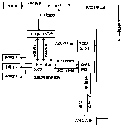
[0014] refer to figure 1. In the embodiment described below, a device for testing the performance of an optical module mainly includes the following parts: a server, a PC, an optical module performance test board and an optical power meter, wherein the PC runs with host computer software, A database is installed on the server, and a USB-to-I2C chip is installed on the test board, which is characterized in that: the PC is connected to the server through the RJ45 network cable, connected to the optical module performance test board through the USB data cable, connected to the optical power meter through the RS232 serial port line, and the optical power The meter is connected to the ROSA optical device through the optical fiber splitter, and the optical module under test is connected to the test board through the golden finger slot. , the other channel is sent to the optical power meter, and the PC obtains the average optical power value of the optical module under test measured...


PUM


Abstract

The invention discloses a device for testing the performance of an optical module and aims at providing a convenient and quick test environment. The invention is realized by the following technical scheme: a PC is connected to a server through an RJ45 network cable, is connected to an optical module performance test board through a USB data line, and is connected to an optical power meter throughan RS232 serial line, the optical power meter is connected to an ROSA optical device through an optical fiber splitter, a tested optical module is connected to the test board through a gold finger slot, the average optical power of the TX end of the tested optical module is divided into two by the optical fiber splitter, one path is sent to the ROSA optical device, and the other path is sent to the optical power meter, the PC obtains the average optical power value of the optical module measured by the optical power meter, and then compares the average optical power value with an optical powerthreshold that have been configured by the server, and determines whether the average optical power value of the tested optical module is within a normal range by using the comparison result. An alarm light visually displays various performance test results of the tested optical module.

Description

technical field [0001] The invention relates to an optical module performance testing device mainly used for photoelectric conversion function in the field of optical communication network. Background technique [0002] In the current optical communication network, the optical module is one of the important devices in the optical fiber communication. As one of the important devices, the optical transceiver module (optical module) is widely used in the Synchronous Optical Network (SONET), Synchronous Digital Hierarchy (SDH ), Asynchronous Transfer Mode (ATM), Fiber Distributed Data Interface (FDDI), and Fast Ethernet and Gigabit Ethernet systems. The main function of the optical module in optical fiber communication is photoelectric conversion, which converts the sent electrical signal into an optical signal; through the optical fiber, the optical signal is converted into an electrical signal for transmission. The optical transceiver module is divided into two parts: the tra...

Claims


Application Information

Patent Timeline
Patent Type & Authority Applications(China)
IPC IPC(8): H04B10/073
CPCH04B10/0731
Inventor 贺海诚
Owner 四川泰瑞创通讯技术股份有限公司
Why Eureka
Try Eureka