
Lens barrel and imaging optical system

a technology of optical system and lens barrel, applied in the field of lens barrel, can solve the problems of difficult adjustment of the position of the electric section with respect to the conductor pattern, difficulty in miniaturizing the lens engagement member, and difficulty in setting the electric section at the predetermined position with respect to the printed board, so as to achieve the effect of increasing the deformation resistan

Active Publication Date: 2014-02-11
KONICA MINOLTA OPTO
View PDF3 Cites 0 Cited by
  • Summary
  • Abstract
  • Description
  • Claims
  • Application Information

AI Technical Summary

Benefits of technology

[0008]The lens barrel and imaging optical system in accordance with the present invention are provided with an electric section having a plurality of sliding portions that slide along a predetermined conductor pattern, the electric section is provided with a thin-sheet electric section body that supports the plurality of sliding portions, and a reinforcing section is provided at the electric section body. Therefore, in such lens barrel and imaging optical system, the reinforcing portion increases the deformation resistance of the electric section body that supports the sliding portions.

Problems solved by technology

For this reason, the dimension of the lens engagement member in the diametrical direction increases and the lens engagement member is difficult to miniaturize.
Furthermore, when the electric section is screwed to the lens engagement member, the position of the electric section with respect to the conductor pattern is difficult to adjust.
For example, where the lens engagement member is displaced with respect to the fixed tube or an error has occurred in the production of the printed board, the electric section is difficult to set at the predetermined position with respect to the printed board.

Method used


Image

  • Lens barrel and imaging optical system
  • Lens barrel and imaging optical system
  • Lens barrel and imaging optical system

Examples


Embodiment Construction

[0019]Embodiments of the present invention will be described hereinbelow with reference to the accompanying drawings. The components assigned with like reference numerals in the drawings are like components and the redundant explanation thereof is omitted.

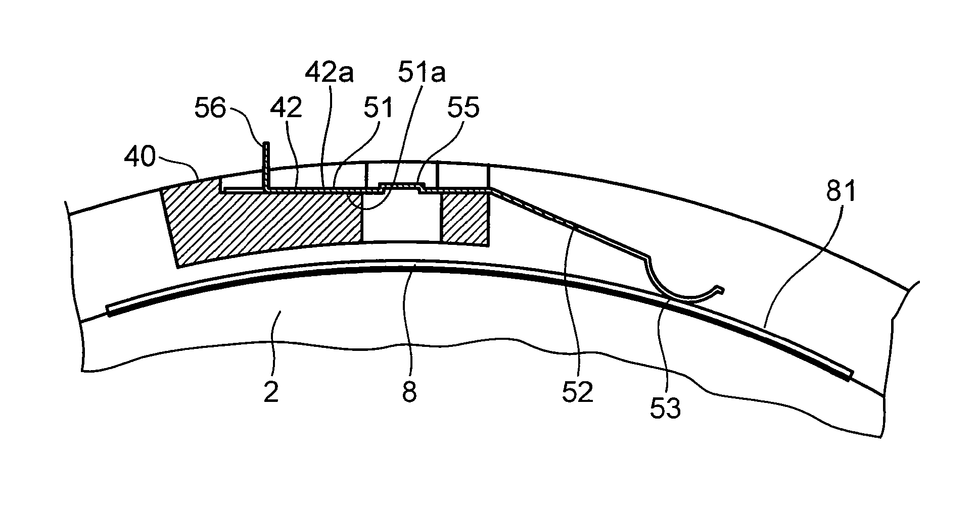
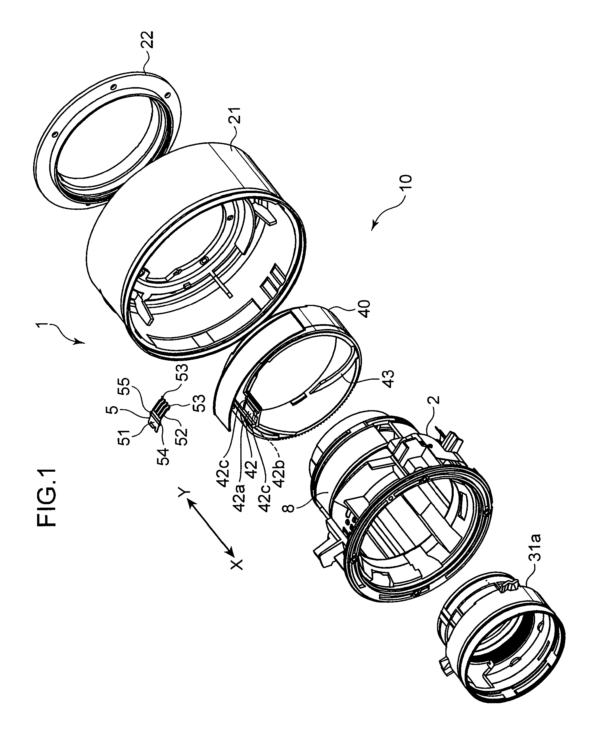
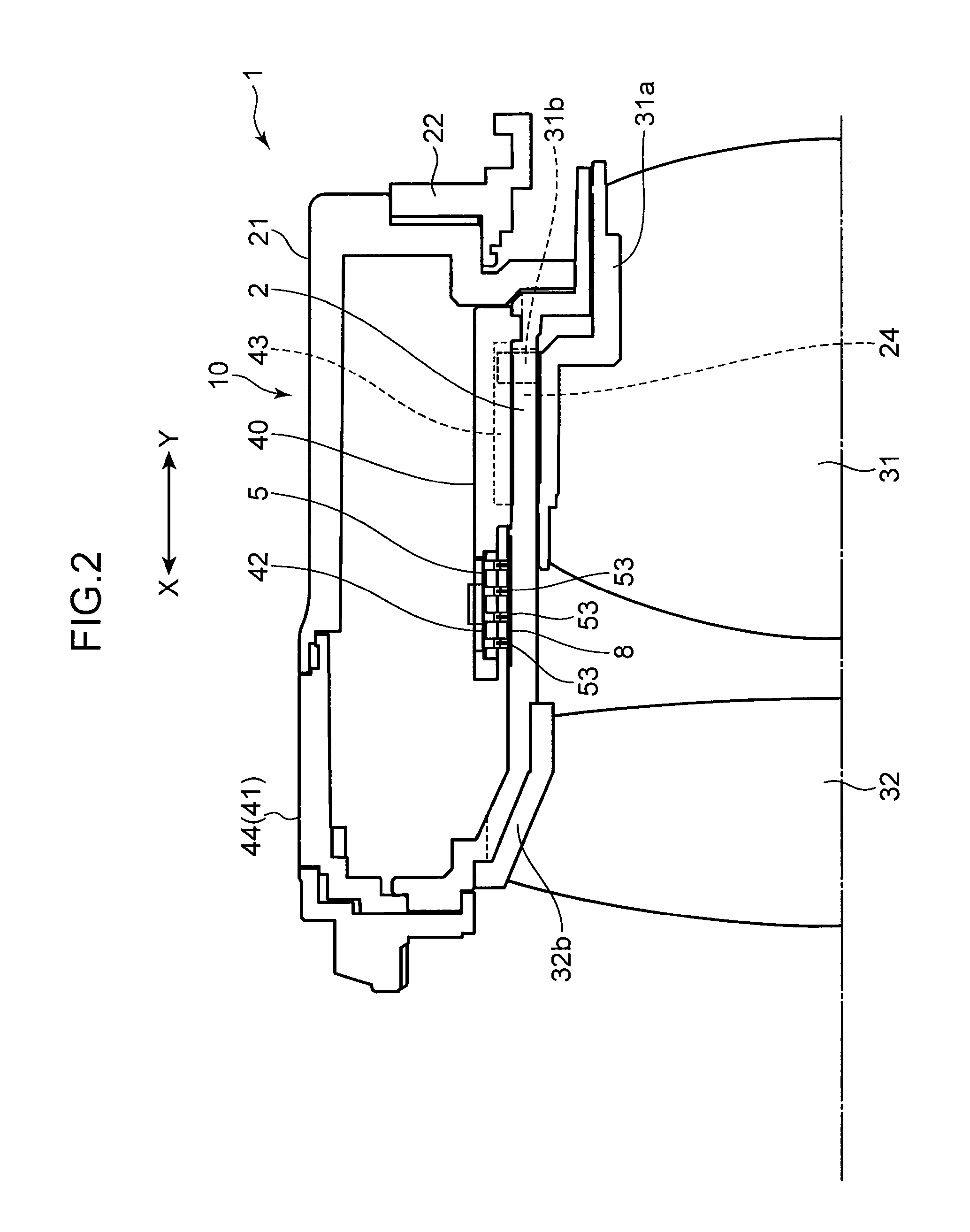
[0020]FIG. 1 is an exploded perspective drawing of the principal portion of the lens barrel in one embodiment. FIG. 2 is a half-sectional view of the imaging optical system provided with the lens barrel in FIG. 1. FIG. 3 is an enlarged plane view of the electric section. The explanation below is conducted by taking the X direction shown in FIGS. 1 and 2 as the direction forward (object side) and Y direction as the direction rearward (image side). FIG. 4 is an enlarged plan view of the principal portion of the lens barrel shown in FIGS. 1 and 2. FIG. 5 is a cross-sectional view along the V-V section in FIG. 4. FIG. 6 is a cross-sectional view along the VI-VI section in FIG. 4.

[0021]As shown in FIG. 2, an imaging optical system of th...


PUM


Abstract

A lens barrel of the present invention is provided with an electric section having a plurality of sliding portions that slide along the predetermined conductor pattern. The electric section is provided with a thin-sheet electric section body supporting the plurality of sliding portions, and a reinforcing portion is provided at the electric section body. Therefore, in the lens barrel 1, the reinforcing portion increases the deformation resistance of the electric section body that supports the sliding portions.

Description

BACKGROUND OF THE INVENTION[0001]1. Field of the Invention[0002]The present invention relates to a lens barrel of a camera or the like and an imaging optical system provided with such lens barrel.[0003]2. Background Art[0004]Lens barrels, for example, of cameras are often provided with a position detection device for performing position control of a movable lens group. For example, when a movable lens group is moved with respect to a fixed tube by drive operating an annular lens engagement member that is engaged with the movable lens group, the lens drive position is detected by detecting the relative positions of the lens engagement member and the fixed tube. The technique for performing such position detection is disclosed, for example, in Japanese Patent Application Publication No. 2007-17679. An encoder device disclosed in Japanese Patent Application Publication No. 2007-17679 is provided with an electric section body in the form of a thin sheet and a plurality of sliding pieces...

Claims


Application Information

Patent Timeline
Patent Type & Authority Patents(United States)
IPC IPC(8): G02B7/02
CPCG02B7/04
Inventor MITANI, YOSHIFUMI
Owner KONICA MINOLTA OPTO
Learn More