
Ratchet wheel for a lashing apparatus

a technology of lashing apparatus and ratchet wheel, which is applied in the direction of manufacturing tools, wire tools, transportation items, etc., can solve the problems of difficult implementation, low practicability, and high cos

Inactive Publication Date: 2006-11-23
YUHUAN TOP SUN MACHINERY TOOL
View PDF9 Cites 7 Cited by
  • Summary
  • Abstract
  • Description
  • Claims
  • Application Information

AI Technical Summary

Benefits of technology

[0013] Compared with the prior art, the advantage of the present invention is to improve the deformation resistance of the reel by changing the shape of the ratchet wheel, and thereby to enhance the mechanical strength of the lashing apparatus. Also, the product of the present structure requires a relatively small increase in cost but presents a significantly improved mechanical performance, compared with the conventional products. It is also safe and reliable with high use values.
is to improve the deformation resistance of the reel by changing the shape of the ratchet wheel, and thereby to enhance the mechanical strength of the lashing apparatus. Also, the product of the present structure requires a relatively small increase in cost but presents a significantly improved mechanical performance, compared with the conventional products. It is also safe and reliable with high use values.

Problems solved by technology

It overcomes the existing technical problems of the prior art that the use of high strength materials and the addition of manufacturing materials to enhance the strength of the ratchet wheel and the like results in a relatively high cost and makes it difficult to implement so that it is not suitable for wide application.

Method used


Image

  • Ratchet wheel for a lashing apparatus
  • Ratchet wheel for a lashing apparatus
  • Ratchet wheel for a lashing apparatus

Examples


embodiment 1

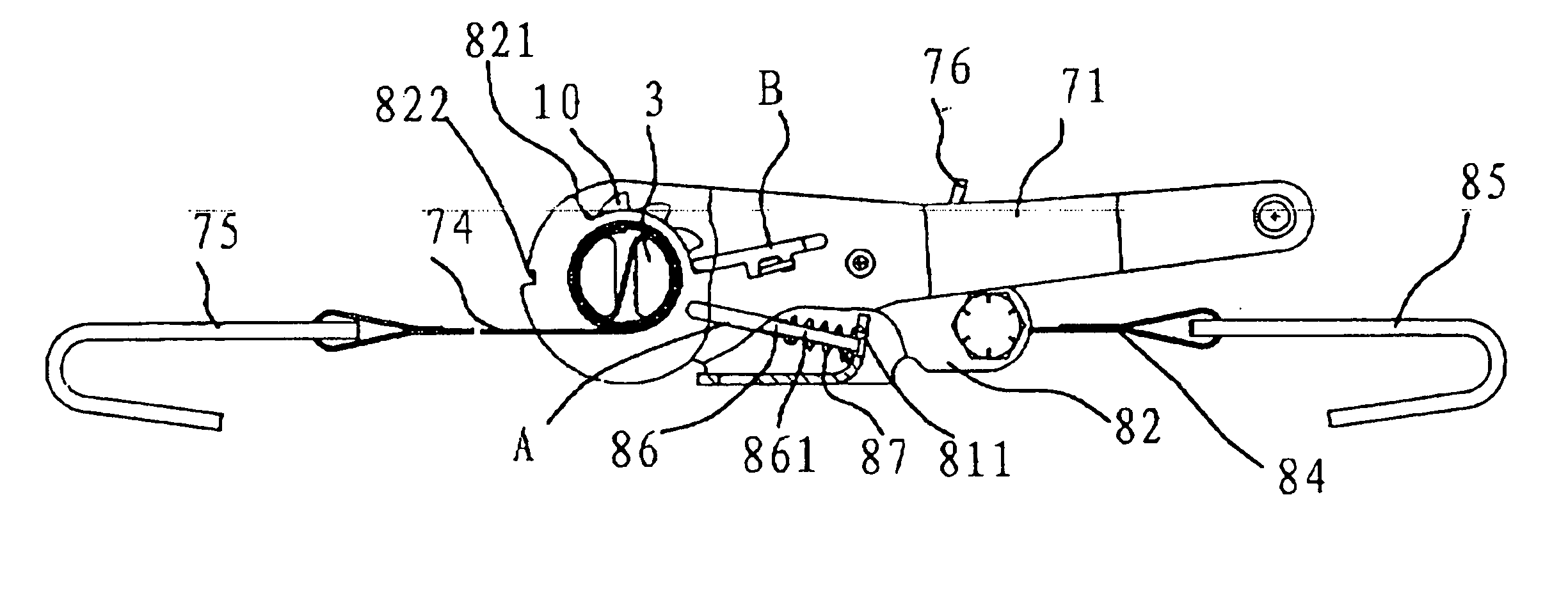
[0024] As shown in FIGS. 12 and 13, a lashing apparatus generally comprises a body 8, a ratchet wheel 10, a baffle 86, a spring 87, a handhold 76, a reel 3, a side piece 71, a mobile strap 74, a positioning strap 84, a positioning hook 85 and a mobile hook 75. The mobile strap 74 is wound around the reel 3, with the mobile hook 75 at the end. The positioning hook 85 and mobile hook 75 at the ends of the lashing apparatus are locked to the goods or the vehicle. The ratchet wheel 10 makes unidirectional rotation by repeatedly turning the side piece 71, so that the mobile strap 74 is wound around the reel 3 continuously to tighten the mobile strap 74. Thus the goods are finally lashed and secured.

[0025] As shown in FIGS. 12 and 13, the body 8 is comprised of a connector 81 and two side plates 82 symmetrically fixed to the sides of the connector 81. The connector 81 is perpendicular to the side plates 82 as an integral. A hinge hole 83 is correspondingly arranged at one end of said two...

embodiment 2

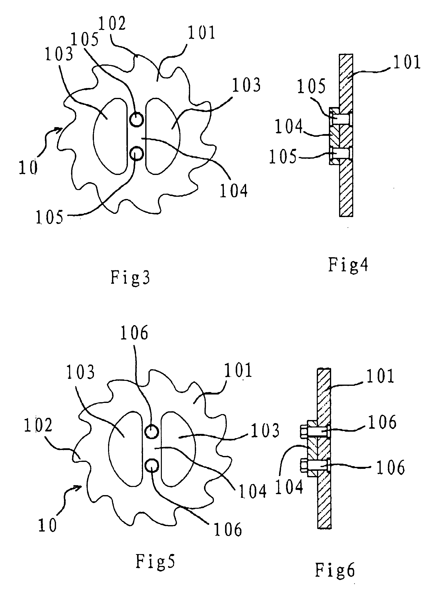
[0043] As shown in the FIGS. 3 and 4, the supporting strip 104 is fixed to the wheel body 101 through rivets 105 according to the Embodiment 2. In such a structure, the connection is secure and the supporting strip 104 has a relatively large protrusion distance from the wheel body 101.

embodiment 3

[0044] As shown in FIGS. 5 and 6, the supporting strip 104 is fixed to the wheel body 101 via a bolt 106 according to the Embodiment 3. Compared with the aforementioned embodiments, the least number of equipments are used for manufacturing the ratchet wheel 10 according to the present embodiment. Having been manufactured, the supporting strip 104 is connected to the wheel body 101 directly by a bolt 106.


PUM


Abstract

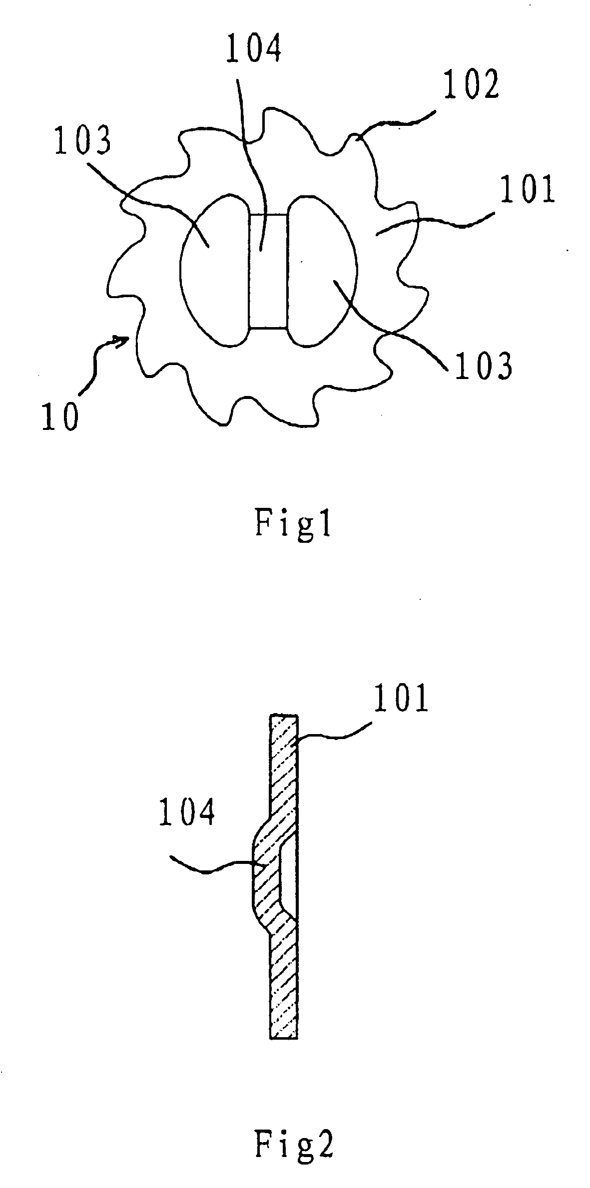
A ratchet wheel for a lashing apparatus in the mechanical technical field is provided as a lashing tool. It addresses the problem in a current lashing apparatus that the mechanical strength of the reel is relatively poor. The ratchet wheel of the present invention comprises a wheel body with ratchet teeth mounted on its outer edge. The wheel body has two shaft holes for the reel to pass through, and a supporting strip between the two shaft holes, which is fixed to the wheel body and protruded to one side of the wheel body. When assembling the ratchet wheel, the two supporting strips of the ratchet wheel are faced towards the inside, so that the distance between the two supporting strips is shortened and thereby the mechanical strength of the reel enhanced. There may be various ways to connect the supporting strips with the wheel body. The ratchet wheel of the present invention is characterized by enhanced distortion resistance of the reel and improved mechanical strength of the lashing apparatus. Furthermore, the lashing apparatus has significantly improved performance but with only a slight increase in the product cost, and it is safe and reliable with high use values.

Description

FIELD OF THE INVENTION [0001] The invention relates to a lashing apparatus in the mechanical technical field, and more particularly to a tool for lashing goods on a vehicle. BACKGROUND OF THE INVENTION [0002] The goods usually need to be lashed during transporting with a vehicle. It is not only inefficient but also strenuous to use the conventional nylon rope or steel rope to lash goods, and it is also difficult to lash these goods tightly. The lashing apparatus has been widely used at present, since it can lash and hold goods rapidly and conveniently. [0003] A great lashing force is required for heavy goods to be transported. This is a challenge to the mechanical strength of the lashing apparatus. In practice, the lashing apparatus may be damaged while an excess force is applied on the strap during lashing the goods, wherein the reel is always the first part to be damaged. Therefore, the mechanical strength of the lashing apparatus can be most effectively enhanced by increasing the...

Claims


Application Information

Patent Timeline
Patent Type & Authority Applications(United States)
IPC IPC(8): B65H75/38B25B25/00B60P7/08
CPCB60P7/083
Inventor RUAN, BOQIN
Owner YUHUAN TOP SUN MACHINERY TOOL
Learn More