
Rotary Body Used for Energy Storage Apparatus, Method of Manufacturing Rotary Body, and Energy Storage Apparatus

a technology of energy storage apparatus and rotary body, which is applied in the direction of magnetic circuit rotating parts, electrical storage systems, magnetic circuit shape/form/construction, etc., can solve the problems of increasing shaft vibration, strain and deformation, and causing vibration of the shaft, so as to increase the amount of energy stored remarkably, easy to manufacture, and easy to set the amount of energy

Inactive Publication Date: 2008-02-07
SIX ONE KAIHATUKIKOU
View PDF3 Cites 1 Cited by
  • Summary
  • Abstract
  • Description
  • Claims
  • Application Information

AI Technical Summary

Benefits of technology

[0012] It is an object of the present invention to provide a rotary body used in an energy storage device, a manufacturing method for a rotary body and an energy storage device where high speed rotation unavailable conventionally is made possible by improving the deformation resistance in the rotary body used in an energy storage device and capable of storing a larger amount of external energy in an energy storage device that stores external energy as the energy of the rotary motion of the rotary body for which the frictional resistance of the bearing parts has been reduced to a high degree using the fishing effect of superconductivity.

Problems solved by technology

However, conventional disk-shaped or ring-shaped flywheels give rise to the following problems.
However, when the periphery of the flywheel reaches a speed of approximately 800 m / sec with disk shaped or ring shaped flywheels, strain and deformation arise in the flywheel itself because of the centrifugal force from the rotation; therefore, the rotational balance of the flywheel breaks down, shaft vibration increases, and the rotational speed cannot be increased above that.
Therefore, it is technically difficult to increase the speed of rotation so that the speed at the periphery of the flywheel is greater than approximately 800 m / sec.

Method used


Image

  • Rotary Body Used for Energy Storage Apparatus, Method of Manufacturing Rotary Body, and Energy Storage Apparatus
  • Rotary Body Used for Energy Storage Apparatus, Method of Manufacturing Rotary Body, and Energy Storage Apparatus
  • Rotary Body Used for Energy Storage Apparatus, Method of Manufacturing Rotary Body, and Energy Storage Apparatus

Examples


Embodiment Construction

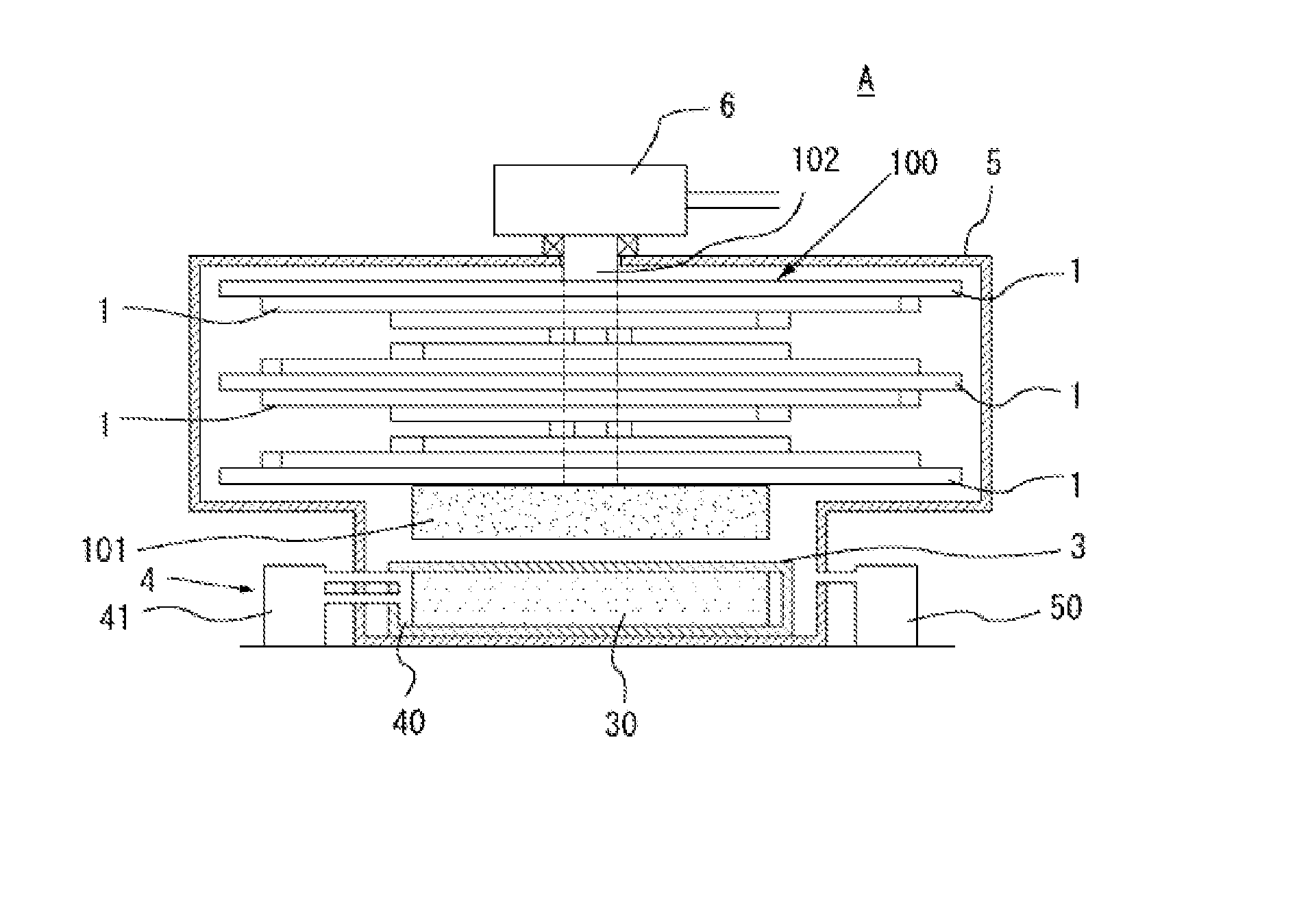
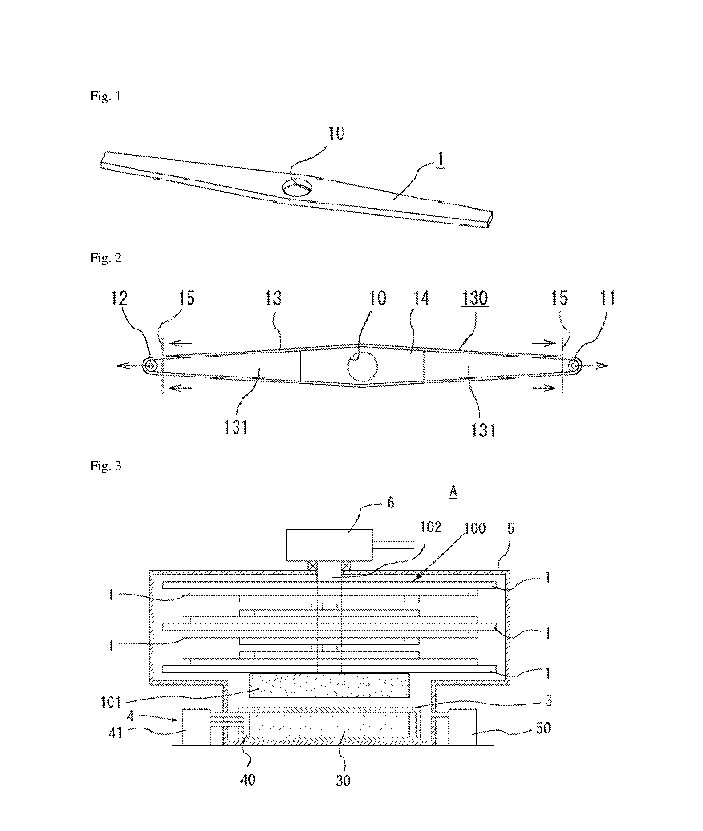
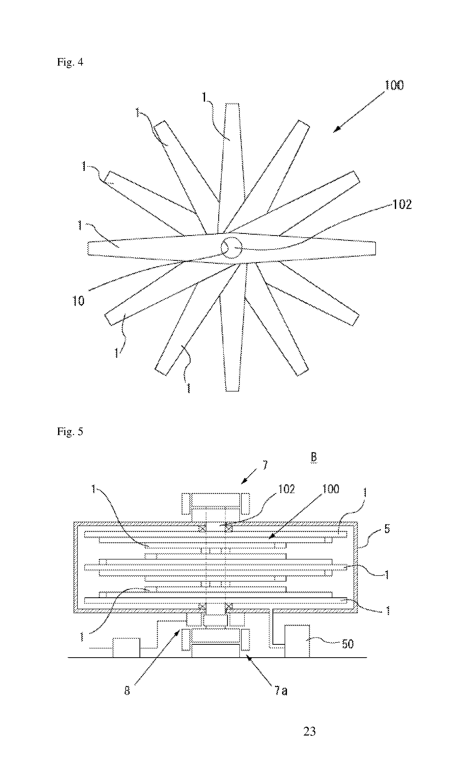
[0042]FIG. 1 shows the structure of a rotary body according to the present invention, and FIG. 2 is a plan view explanatory diagram showing a production method for the rotary body.

[0043] The rotary body 1 is manufactured as a solid from CFRP. The rotary body 1 has a long, thin plate shape or a bar shape. The rotary body 1 has an attachment hole 10 passing through from front to back for attaching a rotary shaft 102 that forms the center of rotation in the middle in the direction of length.

[0044] Moreover, the shape of the attachment hole 10 is a round hole in the present embodiment, but it may be another shape, for example, a square, hexagonal or other polygonal hole. In addition, it may be a hole with a bottom and not a through hole when used singly. Furthermore, the rotary shaft that forms the center of rotation may be directly attached to the rotary body.

[0045] When the rotary body 1 is used as the rotary body for an energy storage device A, it may be used singly or in a plural...


PUM

PropertyMeasurementUnit
speedaaaaaaaaaa
circumferential velocityaaaaaaaaaa
energy storage capacityaaaaaaaaaa

Abstract

A rotary body used in an energy storage device and capable of storing a large amount of external energy is provided in an energy storage device that stores external energy as the energy of the rotary motion of the rotary body for which the frictional resistance of the bearing parts has been reduced to a high degree using the fishing effect of superconductivity. The rotary body is used in an energy storage device capable of storing energy by rotating the rotary body for which the frictional resistance of the bearing parts having floating support that makes use of the fishing effect of superconductivity has been made very small. The rotary body is made of CFRP, and the required compressive stress is applied to it in the direction opposite to the centrifugal force of the rotary body when rotating. The rotary body has a bar-like structure elongated in the direction of the centrifugal force when the rotary body rotates.

Description

CROSS REFERENCE TO PRIOR APPLICATIONS [0001] This is a U.S. national phase application under 35 U.S.C. § 371 of International Patent Application No. PCT / JP2005 / 016278 filed Sep. 5, 2005, and claims the benefit of Japanese Application No. 2004-293113 filed Sep. 6, 2004. The International Application was published on Mar. 16, 2006 as International Publication No. WO 2006 / 028065 under PCT Article 21(2), the content of which is incorporated herein in its entirety.TECHNICAL FIELD [0002] The present invention relates to a rotary body used in an energy storage device, a manufacturing method for a rotary body and an energy storage device. More specifically the present invention relates to a rotary body used in an energy storage device, a manufacturing method for a rotary body and an energy storage device where high speed rotation unavailable conventionally is made possible by improving the deformation resistance in the rotary body used in an energy storage device and making it possible to s...

Claims


Application Information

Patent Timeline
Patent Type & Authority Applications(United States)
IPC IPC(8): H02K7/02
CPCF16C15/00F16C32/0438F16F15/305F16F15/31H02J15/00H02K7/025Y10T74/2132Y02E60/16F16C2361/55Y10T29/49012Y10T74/212Y10T74/2119Y02E40/67Y02E40/60H02J15/007
Inventor OYAMA, TERUTSUGU
Owner SIX ONE KAIHATUKIKOU
Learn More