Heater, image heating device with the heater and image forming apparatus therein

a heating device and heater technology, applied in the direction of heater elements, instruments, electrographic processes, etc., can solve the problems of difficult to set the total resistance of the heat generating resistor, the material having the ptc has a very low volume resistance, and the device parts are difficult to fix. the effect of heat generation distribution unevenness in the longitudinal direction of the heater

Inactive Publication Date: 2014-02-18
CANON KK
View PDF24 Cites 18 Cited by
  • Summary
  • Abstract
  • Description
  • Claims
  • Application Information

AI Technical Summary

Benefits of technology

[0009]According to the present invention, a heat generation distribution unevenness in the longitudinal direction of a heater can be suppressed.
[0010]Further features of the present invention will become apparent from the following description of exemplary embodiments with reference to the attached drawings.

Problems solved by technology

If the temperature of the non-sheet feeding portion excessively rises, parts in the device are damaged, or toner offsets at a high temperature causes in the area corresponding to the non-sheet feeding portion of the small-size sheets when a large-size sheets are printed in a state where the temperature rises at the non-sheet feeding portion.
It is very difficult to set the total resistance of the heat generating resistors formed in one heater to a range usable with a commercial power supply.
Conversely, the material having the PTC has a very low volume resistance.
In the same manner as in the material having the NTC, it is very difficult to set the total resistance of the heat generating resistors in the heater to the range usable with the commercial power supply.

Method used


Image

  • Heater, image heating device with the heater and image forming apparatus therein
  • Heater, image heating device with the heater and image forming apparatus therein
  • Heater, image heating device with the heater and image forming apparatus therein

Examples


example 1

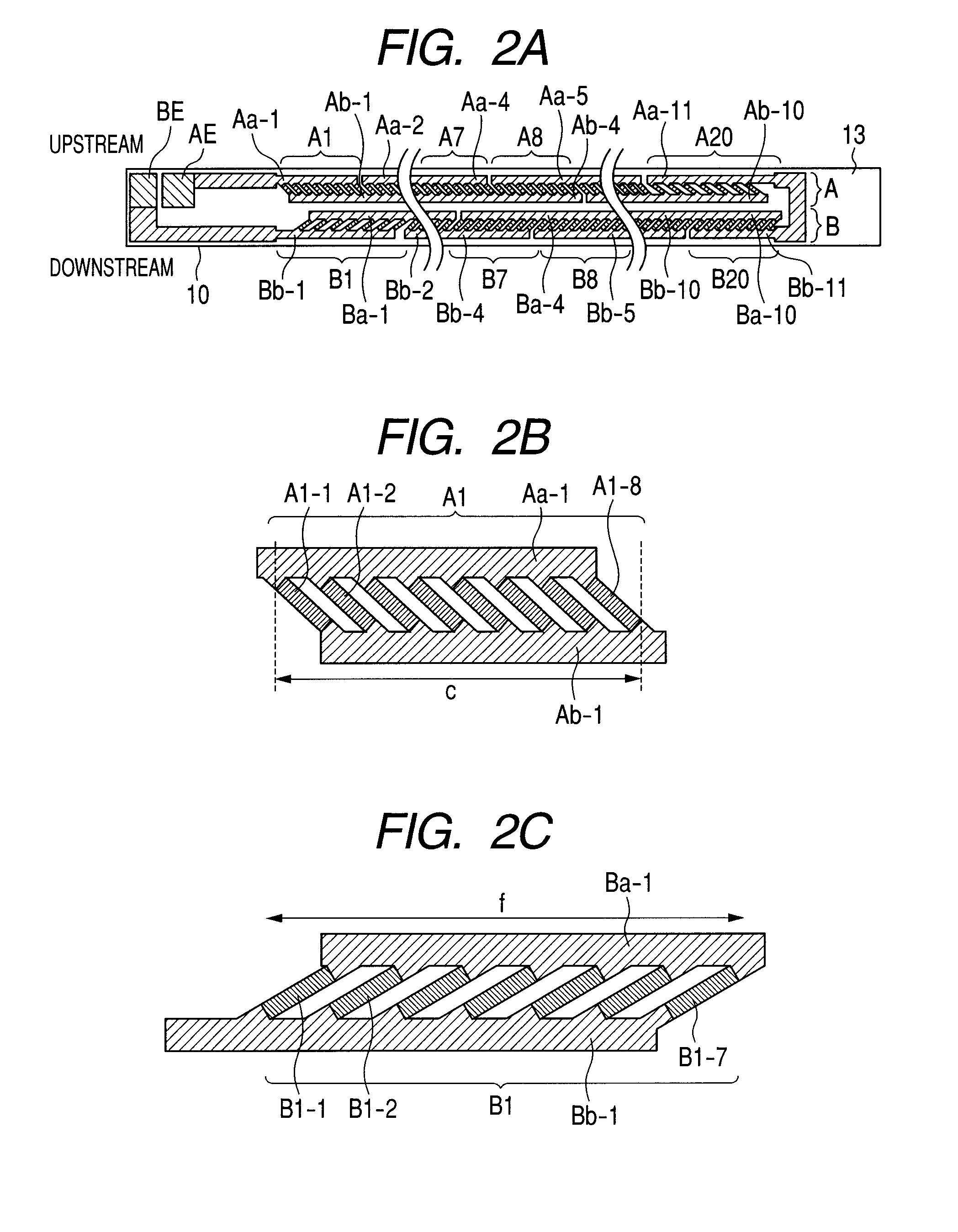
[0029]FIGS. 2A to 2C illustrate diagrams for explaining a heater structure. FIG. 2A is a front view of the heater, FIG. 2B is an enlarged view showing one heat block Al in the heat generation line A, and FIG. 2C is an enlarged view showing one heat block B1 in the heat generation line B. It is to be noted that each of the heat block A1 in the heat generation line A and the heat block B1 in the heat generation line B includes heat generating resistors each having a PTC.

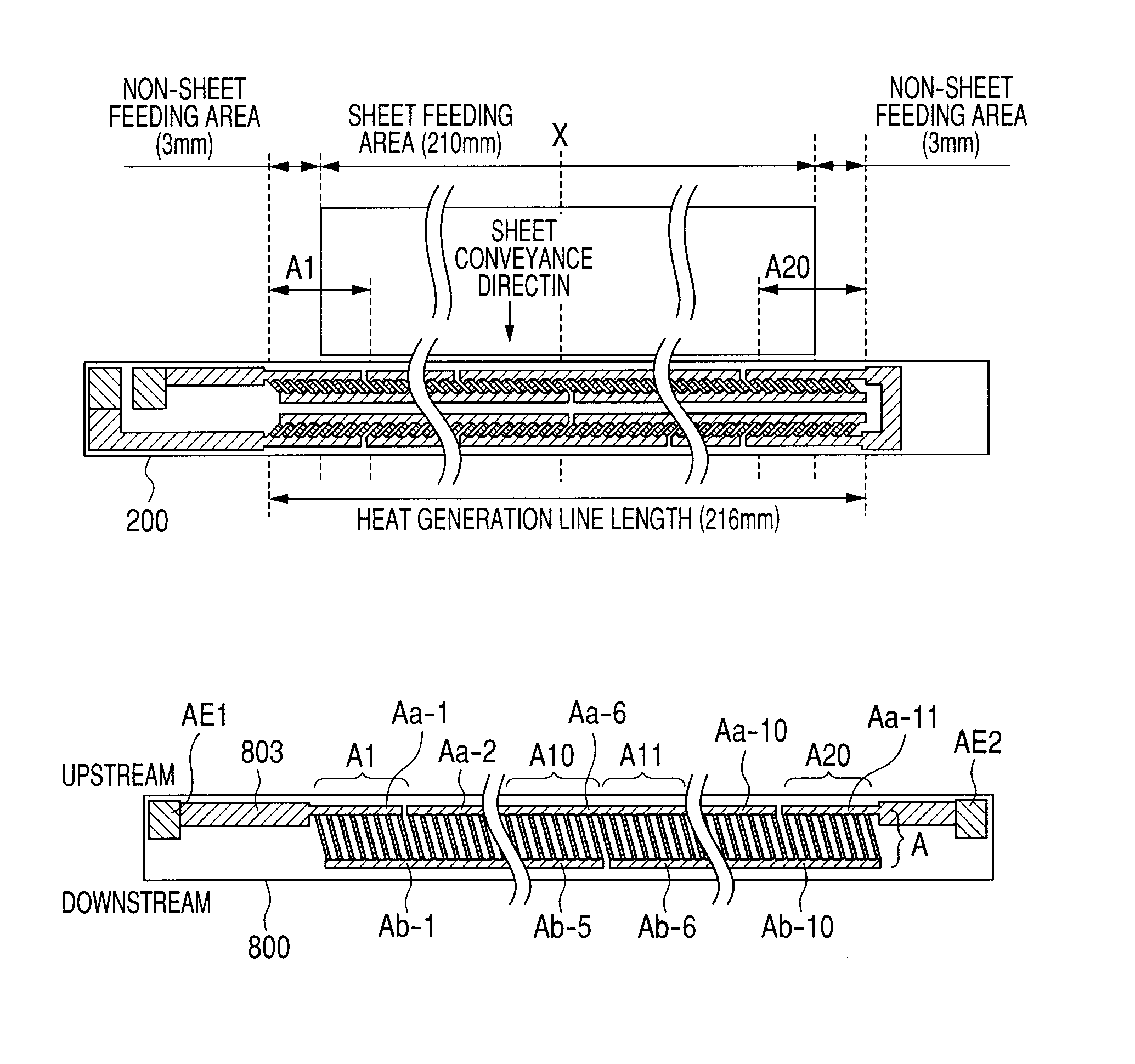
[0030]The heat generation line A (the first row) includes 20 heat blocks A1 to A20, and the heat blocks A1 to A20 are connected in series. The heat generation line B (the second row) includes 20 heat blocks B1 to B20, and the heat blocks B1 to B20 are also connected in series. Moreover, the heat generation lines A and B are electrically connected in series. A power is supplied to the heat generation lines A and B from electrodes AE and BE connected to power supplying connectors.

[0031]The heat generation line A has a co...

example 2

[0046]FIG. 7 is a diagram illustrating the constitution of a heater 20 of Example 2. In the heater 20, two heater drive circuits can independently drive a heat generation line A (a first row) and a heat generation line B (a second row). Therefore, unlike the heater 10 of Example 1, an electrode CE is interconnected between the heat generation line A and the heat generation line B. A power is supplied to the heat generation line A through an electrode AE and the electrode CE, and a power is supplied to the heat generation line B through an electrode BE and the electrode CE. The heater has the same constitution as that of the heater 10 except that the electrode CE is added. Thus, the present invention can be applied to the heater having a constitution in which the heat generation lines A and B can independently be controlled.

example 3

[0047]FIGS. 8A and 8B are diagrams illustrating a constitution of a heater 30 of Example 3. As shown in FIG. 8A, heat blocks A1, A2, B1 and B2 are provided at both ends of the heater 20 along a longitudinal direction in the same manner as in the heater 10 of Example 1. Between the heat block A1 and the heat block A2 of a heat generation line A, a heat block obtained by connecting a plurality of heat generating resistors (A1-1 to Al-8 and A3-1 to A3-8) having a PTC in parallel is not provided, but a heat generation pattern AP including one heat generating resistor is connected in series with the heat blocks A1 and A2. A heat generation line B has a constitution similar to the heat generation line A. The heater 30 also obtains a uniform heat generation distribution along a substrate longitudinal direction. To this end, the heat block A1 of the heat generation line A is shifted from the heat block B1 of the heat generation line B in a heater longitudinal direction so that the block com...


PUM


Abstract

The heater is capable of improving heat generation uniformity in a sheet feeding area while suppressing the temperature rise of a non-sheet feeding portion. Each of heat generation lines includes a plurality of heat blocks in which a plurality of heat generating resistors are electrically connected in parallel between two conductive members. The heat generation lines are arranged in a lateral direction of the substrate, and the heat blocks are arranged so that the end of the heat block in the heat generation line of a first row does not overlap with the end of the heat block in the heat generation line of a second row in a longitudinal direction of a heater.

Description

TECHNICAL FIELD[0001]The present invention relates to a heater which is suitably utilized in a heating fixing device provided in an image forming apparatus such as an electrophotographic copier or an electrophotographic printer, an image heating device on which this heater is mounted, and an image forming apparatus.BACKGROUND ART[0002]As a fixing device provided in a photocopier or a printer, there is a type of the fixing device including an endless belt, a ceramic heater which comes into contact with the inner surface of the endless belt, and a pressure roller which forms a fixing nip portion together with the ceramic heater via the endless belt. When small-size sheets are continuously printed by an image forming apparatus provided with this fixing device, a phenomenon (the temperature rise of a non-sheet feeding portion) in which the temperature gradually rises in an area through which no sheet passes in the longitudinal direction of the fixing nip portion occurs. If the temperatu...

Claims


Application Information

Patent Timeline
Patent Type & Authority Patents(United States)
IPC IPC(8): H05B3/03G03G15/20H05B3/10
CPCH05B3/0095G03G15/2082G03G15/2042G03G15/2053H05B2203/007H05B2203/011H05B3/06H05B2203/016H05B3/0028H05B1/0241H05B3/0019
Inventor SHIMURA, YASUHIRONIHONYANAGI, KOJI
Owner CANON KK
Why Eureka
Try Eureka