Dual locking system for integrated zipper lock

a zipper lock and locking system technology, applied in the field of zipper locks, can solve problems such as the inability to move the latch

Active Publication Date: 2014-03-04
SUN LOCK COMPANY LIMITED -THE-
View PDF12 Cites 65 Cited by
  • Summary
  • Abstract
  • Description
  • Claims
  • Application Information

AI Technical Summary

Benefits of technology

[0022]In accordance with the exemplary embodiment of the invention, in the locked mode of the zipper lock, the combination is not set to the lock open combination on the combination locking mechanism, and therefore notches on the clutches that are rotably affixed to the combination dials are not aligned with protrusions extending from a locking plate. Therefore, the locking plate cannot move, and a user of the zipper lock cannot push a release actuator because a tail of the blocking plate blocks the movement of a actuation plate operatively connected to the release actuator. Since the actuation plate cannot be moved, the user cannot move the latch-control plate, and therefore cannot move the latch to its release and unlock position. Since the latch is in the locked position, a locking finger of the latch is engaged into a locking area formed by the left locking head and the right locking head. This engagement thereby prevents opening of the zipper lock.
[0024]As the latch-control plate moves leftward, the slope of the latch-control plate will contact the slope of the latch. Again, these slopes will help to transfer the horizontal movement from the latch-control plate to a vertical movement of the latch. As the latch moves upward the locking finger will no longer be in contact with the locking area of the left locking head and right locking head. As the user pushes the actuator more leftward, since the latch has moved upward and the locking finger has been detached from the locking area, the wall of the latch-control plate will be in contact with the ends of the left locking head and the right locking head. Therefore, the left locking head and right locking head will move leftward. As the left locking head and right locking head move leftward, the zipper pull tabs can be released away from the body of the zipper lock.
[0025]In accordance with the exemplary embodiment of the invention, the zipper lock may include one or more blocking plates that have two functions for the zipper lock. First, the one or more blocking plates may help the zipper pull tabs to pop up and out of the body of the zipper lock when the left and right locking heads move leftward. Since a blocking plate spring pushes each of the one or more blocking plates upward, the zipper pull tabs can pop away from the body when the left and right locking heads moves leftward. The second function of the one or more blocking plate is that each blocking plate does not allow the left and right locking heads to move back to the locking position once it is being opened by either of the combination locking mechanism or the key locking mechanism. As the left and right locking heads move leftward, the blocking plates move upward. As the blocking plates move upward, a wall of the blocking plates will contact a plane of each of the left locking head and right locking head. Therefore, the wall of each of the blocking plates act to restrict the left and right locking heads from moving back to the locking position. The left and right locking heads can move back to the locking position when the zipper pull tabs are inserted and depress the blocking plates downward. The walls of the blocking plates will no longer contact to the planes of the left and right locking heads. Therefore, the left and right locking heads springs will force the locking latches to move back to the locking position.
[0030]In accordance with the exemplary embodiment of the present invention, the zipper lock further includes one or more blocking plates that are configured to push the zipper pull tabs out of the body of the zipper lock when the left and right locking heads are released from the locked position. A wall of each of the blocking plates restricts the left and right locking heads from returning to the locking position. This system of blocking the zipper locking heads by using a blocking plate or any form of blocking element after unlock allows the lock to remain in the unlock mode after key is withdrawn from the cylinder and hence has fulfilled a non-key captive requirement.

Problems solved by technology

Therefore, the locking plate cannot move, and a user of the zipper lock cannot push a release actuator because a tail of the blocking plate blocks the movement of a actuation plate operatively connected to the release actuator.
Since the actuation plate cannot be moved, the user cannot move the latch-control plate, and therefore cannot move the latch to its release and unlock position.

Method used


Image

  • Dual locking system for integrated zipper lock
  • Dual locking system for integrated zipper lock
  • Dual locking system for integrated zipper lock

Examples


Embodiment Construction

[0082]The present invention now will be described more fully hereinafter with reference to the accompanying figures, in which exemplary embodiments of the invention are shown. The invention may, however, be embodied in many different forms and should not be construed as limited to the embodiments set forth herein. Like reference numerals refer to like elements throughout.

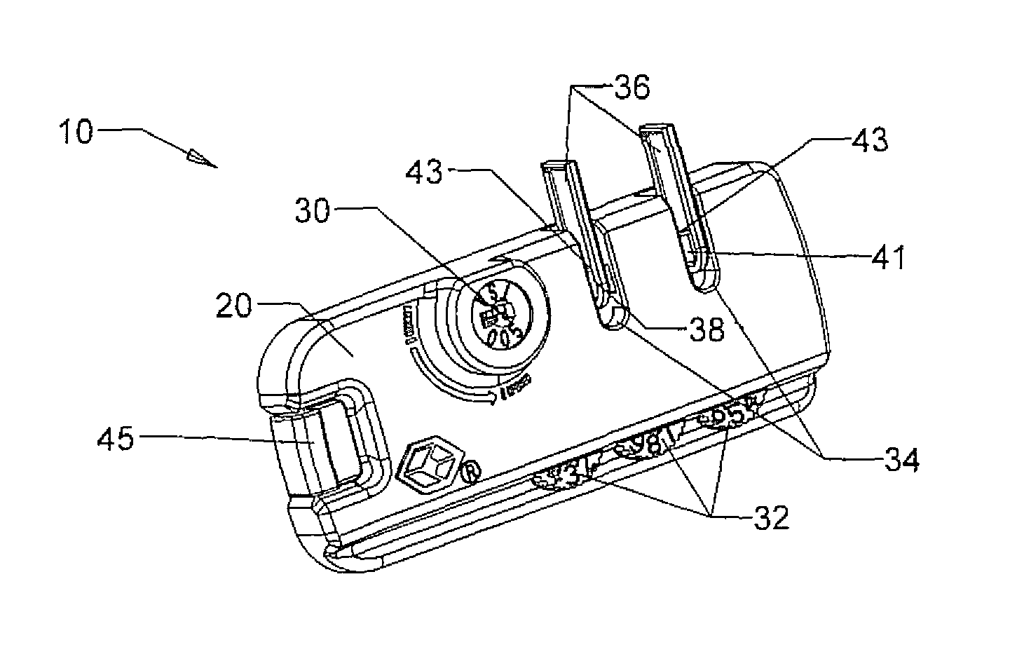
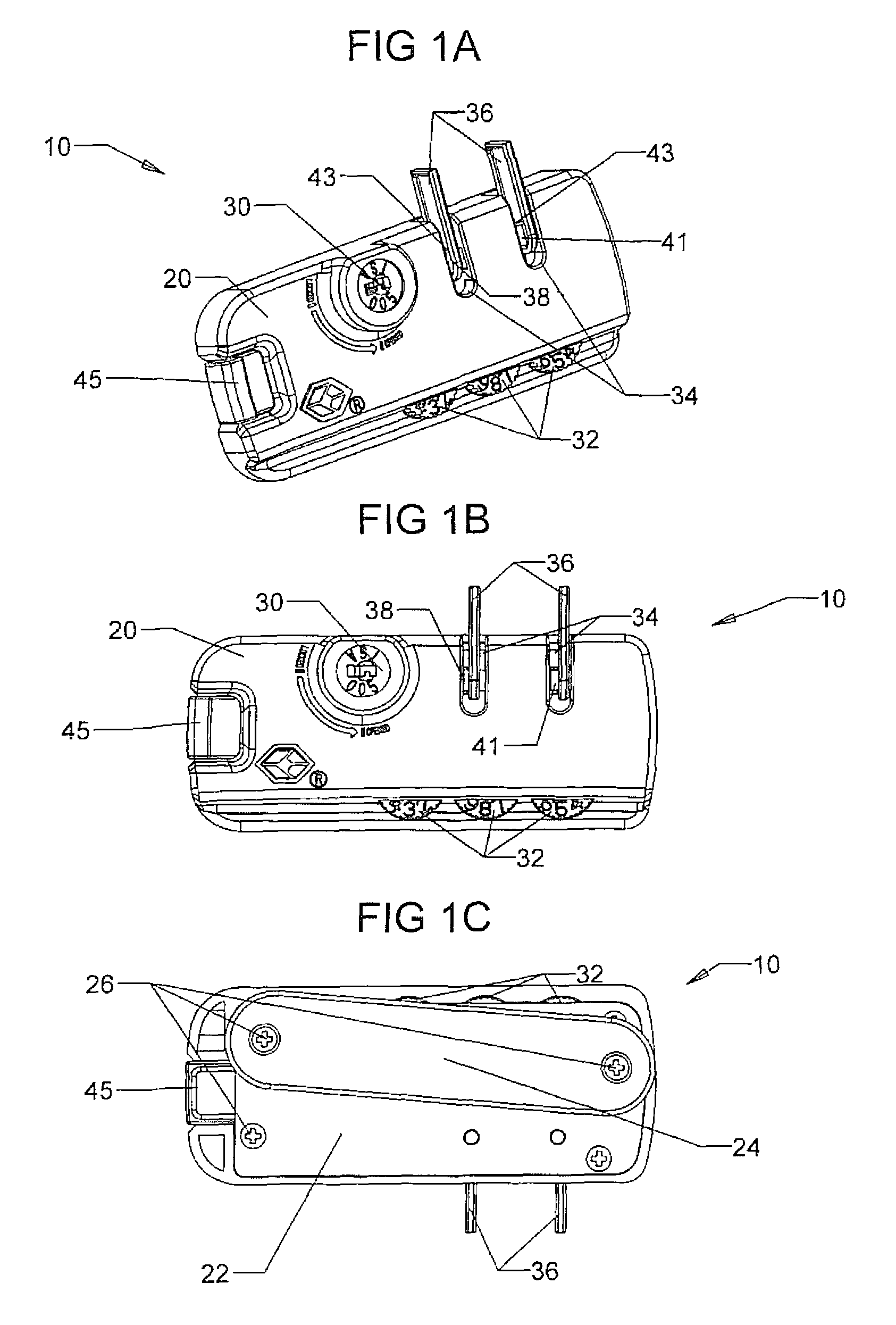
[0083]Referring first to FIGS. 1A-1C, therein illustrated is an exemplary zipper lock generally indicated by the numeral 10 of the present invention. The zipper lock 10 includes a body 20 and a backing plate 22 that together form a housing / cover for the internal components of the zipper lock 10 that will be discussed further below. The zipper lock 10 also includes a back cover 24 that also forms part of the housing / cover for the internal components of the zipper lock 10. The backing plate 22, back cover 24 and body 20 may be affixed together by one or more fasteners 26, and the fasteners 26 may be such that they can...


PUM


Abstract

The present invention is directed to a zipper lock that includes an actuator operatively connected to an actuation plate and a blocking plate positioned relative to the actuation plate so as to at least partially block the movement of the actuation plate when the zipper lock is in the locked configuration. The actuator and the actuation plate are configured for interaction so as to transform movement of the actuator into movement of the actuation plate when the zipper lock is in an unlocked configuration. The zipper lock further includes a latch control plate operatively connected to the actuator, and operatively connected to a latch, in which the latch includes a locking finger configured for locking engagement with at least one locking head that is configured to retain a zipper pull tab to the zipper lock when the zipper lock is in a locked configuration.

Description

CROSS-REFERENCE TO RELATED APPLICATIONS[0001]This application claims priority to U.S. Provisional Appl. No. 61 / 574,764 filed Aug. 8, 2011, which is hereby incorporated by reference in its entirely.BACKGROUND OF THE INVENTION[0002]1. Field of the Invention[0003]This invention relates to locks, and more particularly, to a zipper lock with a dual locking system.[0004]2. Description of Related Art[0005]Numerous padlock constructions have been developed and are widely employed by individuals to prevent unauthorized persons from gaining access to any particular item or area which has been closed and locked. Although many locks are constructed to be opened by a key, numerous combination lock constructions have been developed which are opened by knowledge of a particular combination.[0006]One particular type of combination lock that has become very popular due to its ease and convenience of use is a combination lock which employs a plurality of rotatable independent dials, each of which for...

Claims


Application Information

Patent Timeline
Patent Type & Authority Patents(United States)
IPC IPC(8): E05B37/14
CPCE05B37/0058E05B37/0034E05B35/105E05B35/10E05B65/52E05B37/12Y10T70/5066Y10T70/415Y10T70/5053Y10T70/5031Y10T70/7141Y10T70/7147
Inventor LAI, KARL
Owner SUN LOCK COMPANY LIMITED -THE-
Why Eureka
Try Eureka