
Vacuum pump

a vacuum pump and vacuum technology, applied in the field of vacuum pumps, can solve the problems of large power consumption, difficult and/or costly, and difficult to achieve the tight axial clearance between the rotor and stator components of the siegbahn pumping mechanism, and achieve the required level of pumping performan

Active Publication Date: 2014-03-04
EDWARDS LTD
View PDF35 Cites 6 Cited by
  • Summary
  • Abstract
  • Description
  • Claims
  • Application Information

AI Technical Summary

Benefits of technology

The invention is a vacuum pump with a bearing arrangement that supports the drive shaft in both radial and axial directions. The use of a resilient support helps to reduce the cost and complexity of the bearing arrangement, while also allowing for tight tolerance control and positioning of the bearing. The flexible members of the resilient support act as leaf springs, providing integrated leaf springs that determine the radial stiffness of the resilient support. By designing the radial flexibility of the resilient support to match the vibration characteristics of the drive shaft, the pump can achieve a lower level of vibration, without the need for expensive high speed balancing. Overall, this invention provides a more cost-effective and efficient vacuum pump.

Problems solved by technology

However, for a given rotor-to-stator clearance, a Siegbahn pumping mechanism typically requires more pumping stages to achieve the same levels of compression and pumping speed as a Holweck pumping mechanism.
Furthermore, a Siegbahn pumping mechanism requires tight clearances to be achieved in an axial direction, otherwise more pumping stages—and thus greater power consumption—will be required to achieve the required level of pumping performance.
Achieving tight axial clearances between the rotor and stator components of a Siegbahn pumping mechanism can be relatively difficult and / or costly.
A relatively complex and expensive magnetic bearing arrangement comprising upper and lower radial magnetic bearings, and an axial magnetic bearing, is provided for supporting the drive shaft out of contact with the stator, and for maintaining the required axial clearances between the rotor and stator disks.

Method used


Image

  • Vacuum pump
  • Vacuum pump
  • Vacuum pump

Examples


Embodiment Construction

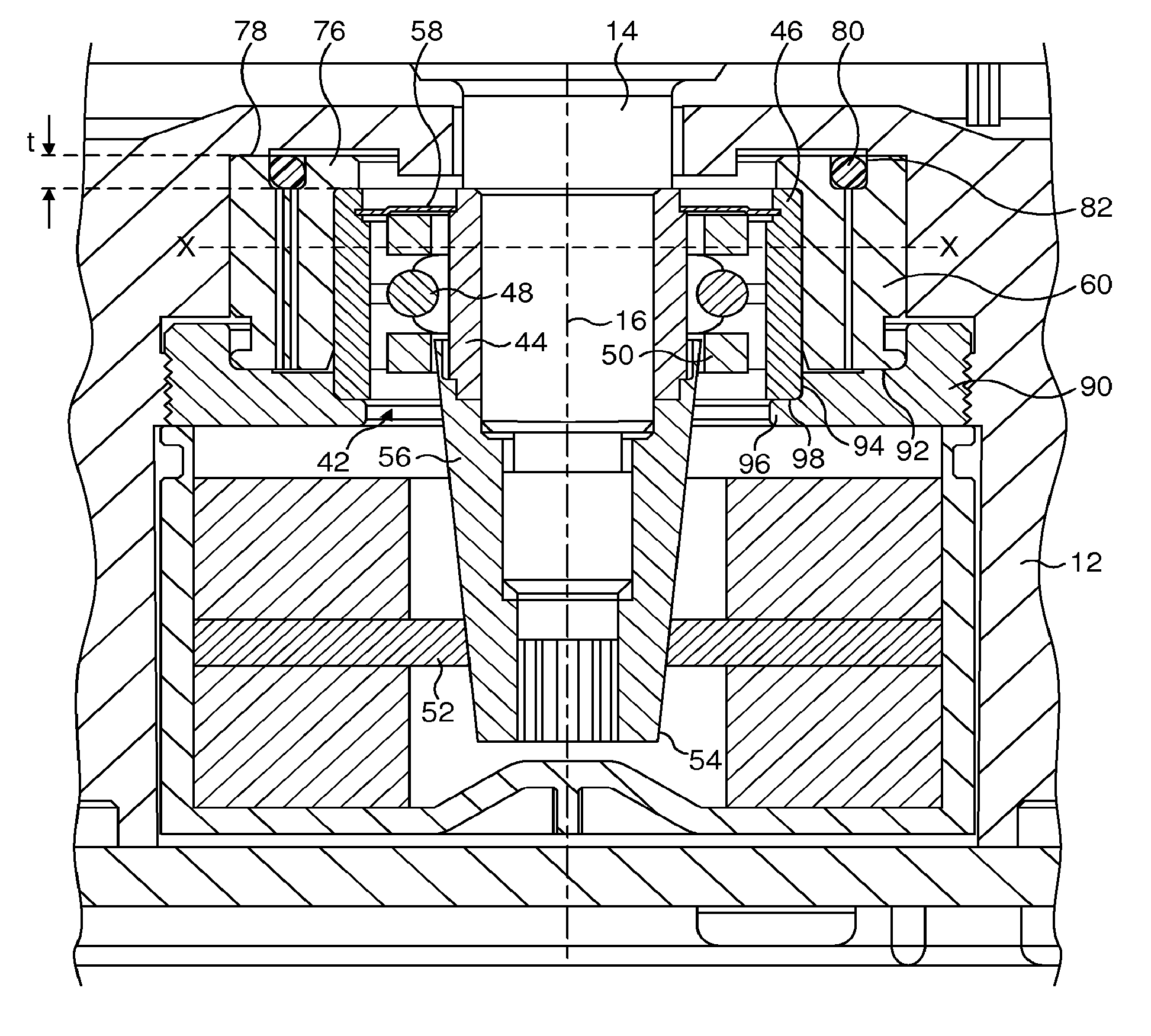
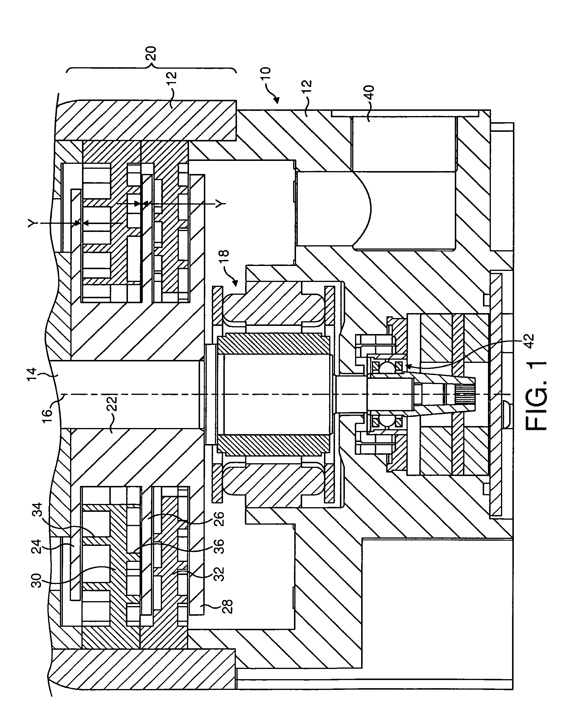
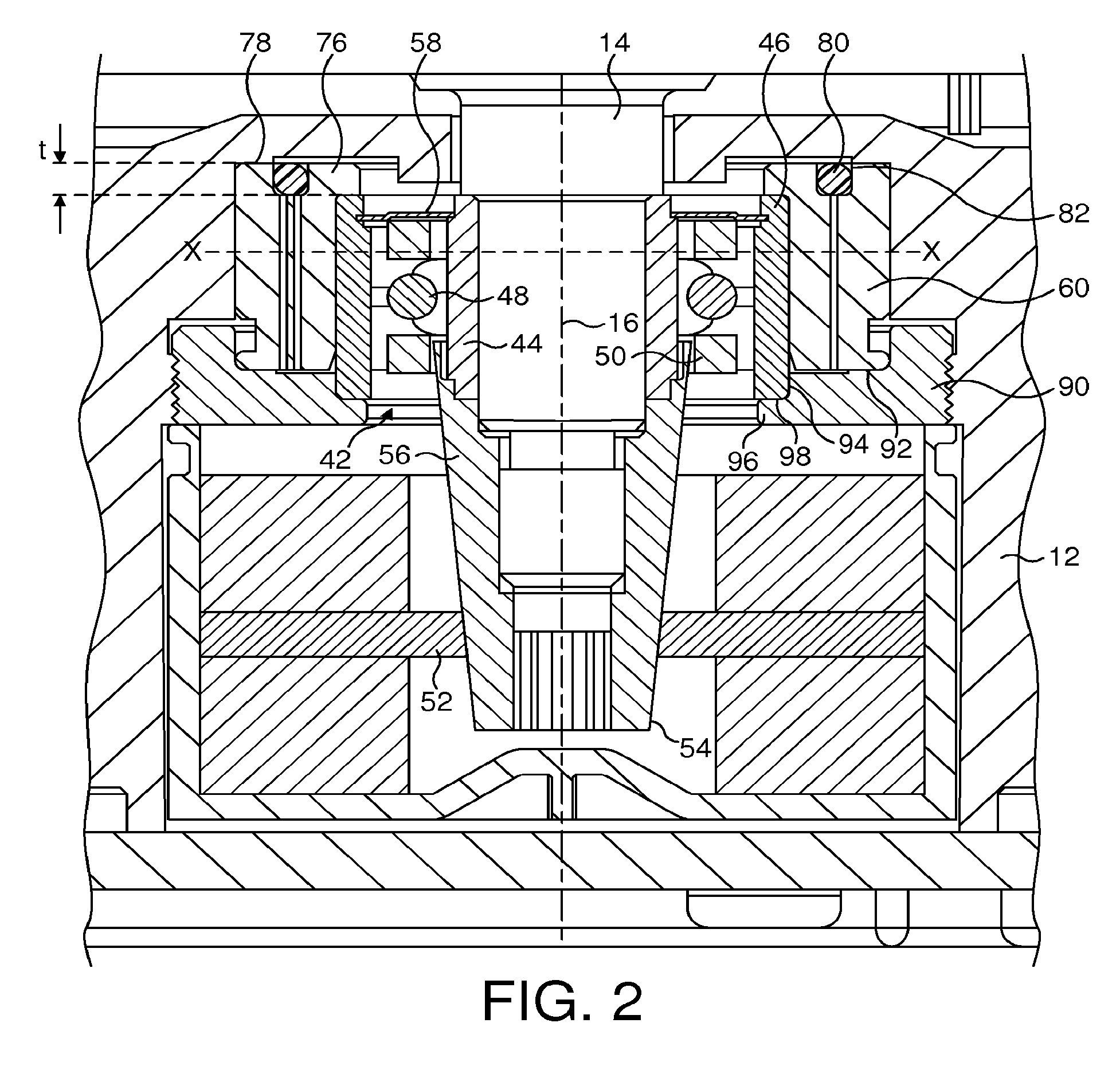
[0010]The present invention provides a vacuum pump comprising a housing, a drive shaft supported by a bearing arrangement for rotation relative to the housing, and a pumping mechanism comprising a stator component mounted on the housing and a rotor component mounted on the drive shaft axially proximate the stator component, the bearing arrangement comprising a bearing supported in both radial and axial directions by a metallic resilient support, comprising inner and outer annular portions connected by a plurality of flexible members, so that there is a fixed relation between the inner race of the bearing and the outer portion of the resilient support to determine the axial clearance between the rotor and stator components of the pumping mechanism.

[0011]The use of a resilient support for both supporting the drive shaft in the axial and radial directions, and for determining the axial clearance between the rotor and stator components of the pumping mechanism, can significantly reduce ...


PUM


Abstract

A vacuum pump comprises a housing, a drive shaft supported by a beating arrangement for rotation relative to the housing about an axis, and a pumping mechanism comprising a stator component mounted on the housing and a disk-shaped rotor component mounted on the drive shaft axially proximate the stator component. The bearing arrangement comprises a bearing supported in both radial and axial directions by a resilient support, comprising inner and outer annular portions connected by a plurality of flexible members, so that there is a fixed relation between the inner race of the bearing and the outer portion of the resilient support to determine the axial clearance between the rotor and stator components of the pumping mechanism.

Description

FIELD OF THE INVENTION[0001]The present invention relates to a vacuum pump, and finds particular, but not exclusive, use in a vacuum pump comprising a molecular drag pumping mechanism.BACKGROUND OF THE INVENTION[0002]Molecular drag pumping mechanisms operate on the general principle that, at low pressures, gas molecules striking a fast moving surface can be given a velocity component from the moving surface. As a result, the molecules tend to take up the same direction of motion as the surface against which they strike, which urges the molecules through the pump and produces a relatively higher pressure in the vicinity of the pump exhaust.[0003]These pumping mechanisms generally comprise a rotor and a stator provided with one or more helical or spiral channels opposing the rotor. Types of molecular drag pumping mechanisms include a Holweck pumping mechanism comprising two co-axial cylinders of different diameters defining a helical gas path therebetween by means of a helical thread ...

Claims


Application Information

Patent Timeline
IPC IPC(8): F01D25/16
CPCF04D17/168F04D29/668F04D29/056
Inventor TOLLNER, MARTIN ERNSTBREWSTER, BARRIE DUDLEY
Owner EDWARDS LTD
Learn More