Eureka AIR delivers breakthrough ideas for toughest innovation challenges, trusted by R&D personnel around the world.

Wireless energy transfer for photovoltaic panels

a photovoltaic panel and wireless technology, applied in the direction of inductance, driver interaction, electric devices, etc., can solve the problems of high cost of solar power systems, hampered adoption of traditional residential and commercial solar photovoltaic (pv) panel installations, and limited wireless energy transfer systems of the past. to achieve the effect of reducing the cost and complexity of the solar panel installation process and reducing the factors driving the high cost of solar pv panel installations

Active Publication Date: 2015-05-19
WITRICITY CORP
View PDF803 Cites 26 Cited by
  • Summary
  • Abstract
  • Description
  • Claims
  • Application Information

AI Technical Summary

Benefits of technology

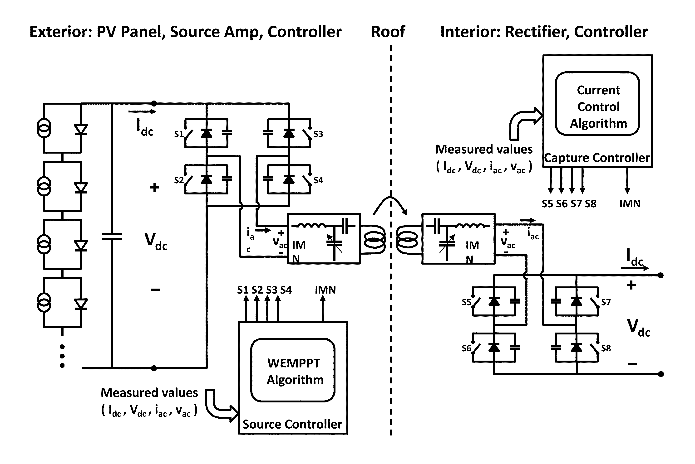
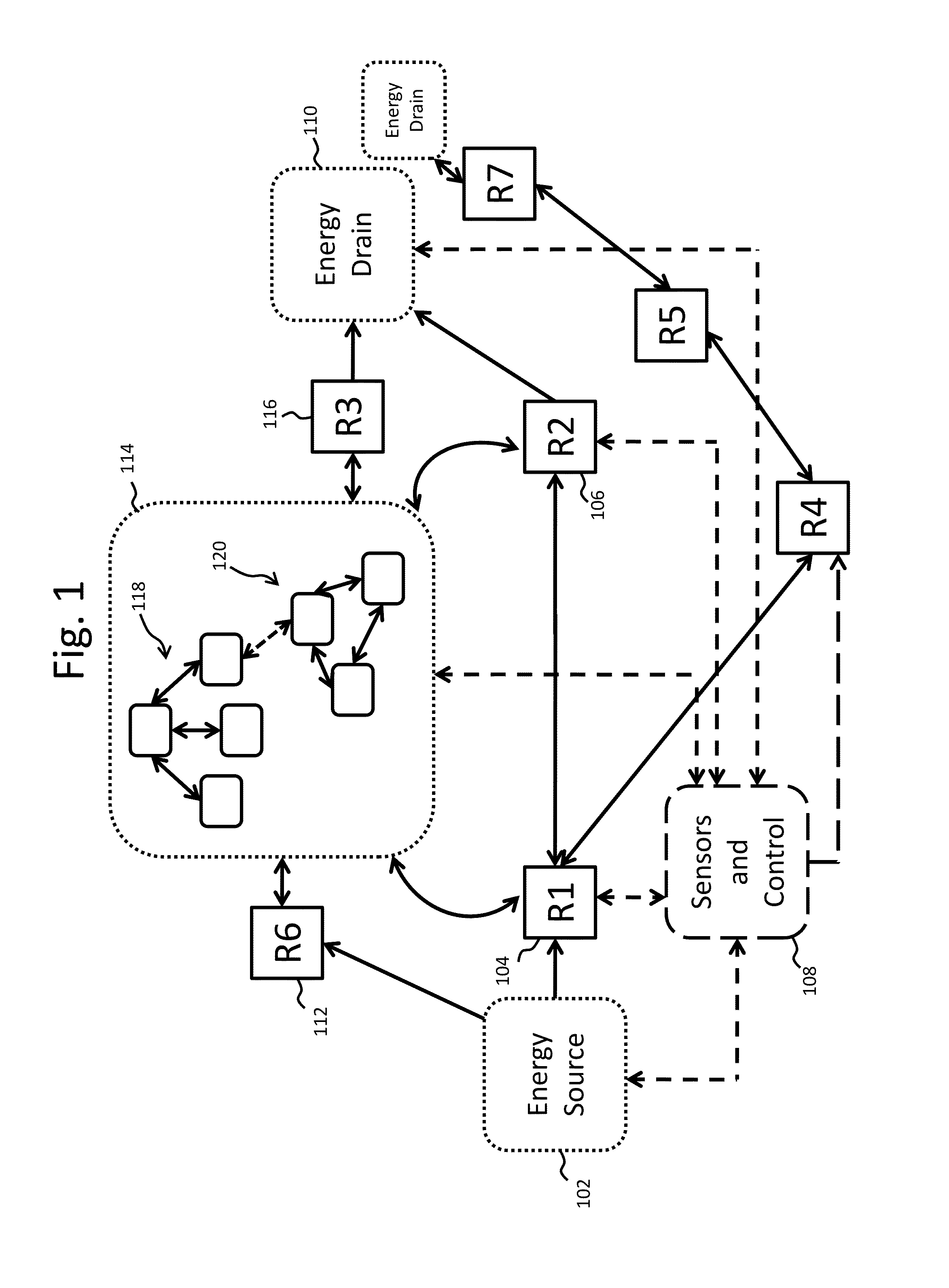
[0041]Adding the capability to PV panels of wireless energy transfer using coupled resonators may substantially reduce the cost and complexity of the solar panel installation process. In embodiments, individual panels with associated MPPT circuits and associated wireless energy sources can be placed on a roof. Corresponding wireless energy capture devices may be located beneath the roof. Such a configuration may mitigate the factors driving the high cost of solar PV panel installations. For example, there may be less need for electrical wiring on the roof and for the associated roof penetrations. Fewer installation personnel may need to be trained and insured for roof-top work. And the PV panels might not need electrical feedthroughs and the associated weather seals.
[0044]In another embodiment extraction of electrical energy from PV panels without losing substantial energy intended for wireless transfer is achieved with a wireless energy source that can be configured for energy transfer between resonators while also applying an equivalent load resistance to a PV panel for optimal energy extraction. Such a wireless source can efficiently transfer energy from a PV panel to a wireless capture device over a wider range of environmental conditions than is currently possible. Such a wireless energy source is referred to herein as a “wireless energy maximum power point tracker (WEMPPT).”

Problems solved by technology

Prior art wireless energy transfer systems have been limited by a variety of factors including concerns over user safety, low energy transfer efficiencies and restrictive physical proximity / alignment tolerances for the energy supply and sink components.
It is generally acknowledged that the adoption of traditional residential and commercial solar photovoltaic (PV) panel installations have been hampered by the high costs of these solar power systems.
Recent estimates suggest that as much as 50% of the system costs are associated with the solar PV panel installation process.
The factors driving the high cost of solar PV panel installations may include:Roof Danger: Installation work is generally performed on a roof, and such work may carry a substantial premium for Liability and Workman's Compensation Insurance due to the inherent danger.Highly Skilled Labor: The complexity of solar PV panel installation may require an ensemble of highly trained tradesmen (roofers, carpenters, and electricians), contractors, and professional engineers, who command premium rates.Site-Specific Design: Each installation may require site-specific engineering to optimize panel location, string design, and wiring configurations, to accommodate the individual roof pitch, solar orientation, and other building specific features.
Without such site-specific optimization, output efficiency may be dramatically lower than expected.Roof and Building Penetrations: Running wiring through roof structures or exterior walls may be an expensive and potentially trouble prone operation, compromising the weather tightness of the building.High Fixed Costs: The installation costs may have a high fixed cost component, which means that the scale of the PV installation must be large enough (often 2 kW-3 kW) to amortize the installation costs.
As a result, typical residential solar PV systems may cost upwards of $20,000, and may have unsubsidized payback periods exceeding twenty (20) years.
In addition to high installation costs, traditional, wired, PV panels may be difficult to reconfigure and unreliable.
These panels may need to be permanently wired into fixed locations making changes in configurations or repositioning troublesome since it may require rewiring and extending the electrical connections.
In addition wired connections may make weatherproofing and sealing of the wires, connectors and circuit components in PV systems more difficult and may result in more failure points in the installed systems which may be exposed to extreme environmental conditions including extreme temperatures, high winds, rain, high ultra violet radiation, and the like.
One particular challenge in applying wireless energy transfer to PV panels is the problem of optimizing the wireless energy transfer without degrading the ability to extract maximum electrical energy from a PV panel or string of panels.
The problem is that the equivalent load resistance varies as environmental conditions change and the resistance at any given time may not be conducive to wireless energy transfer.
Variations in the current or voltage at the input of a wireless energy source may degrade the efficiency of wireless energy transfer to a wireless energy capture device.

Method used


Image

  • Wireless energy transfer for photovoltaic panels
  • Wireless energy transfer for photovoltaic panels
  • Wireless energy transfer for photovoltaic panels

Examples


Embodiment Construction

[0104]As described above, this disclosure relates to wireless energy transfer using coupled electromagnetic resonators. However, such energy transfer is not restricted to electromagnetic resonators, and the wireless energy transfer systems described herein are more general and may be implemented using a wide variety of resonators and resonant objects.

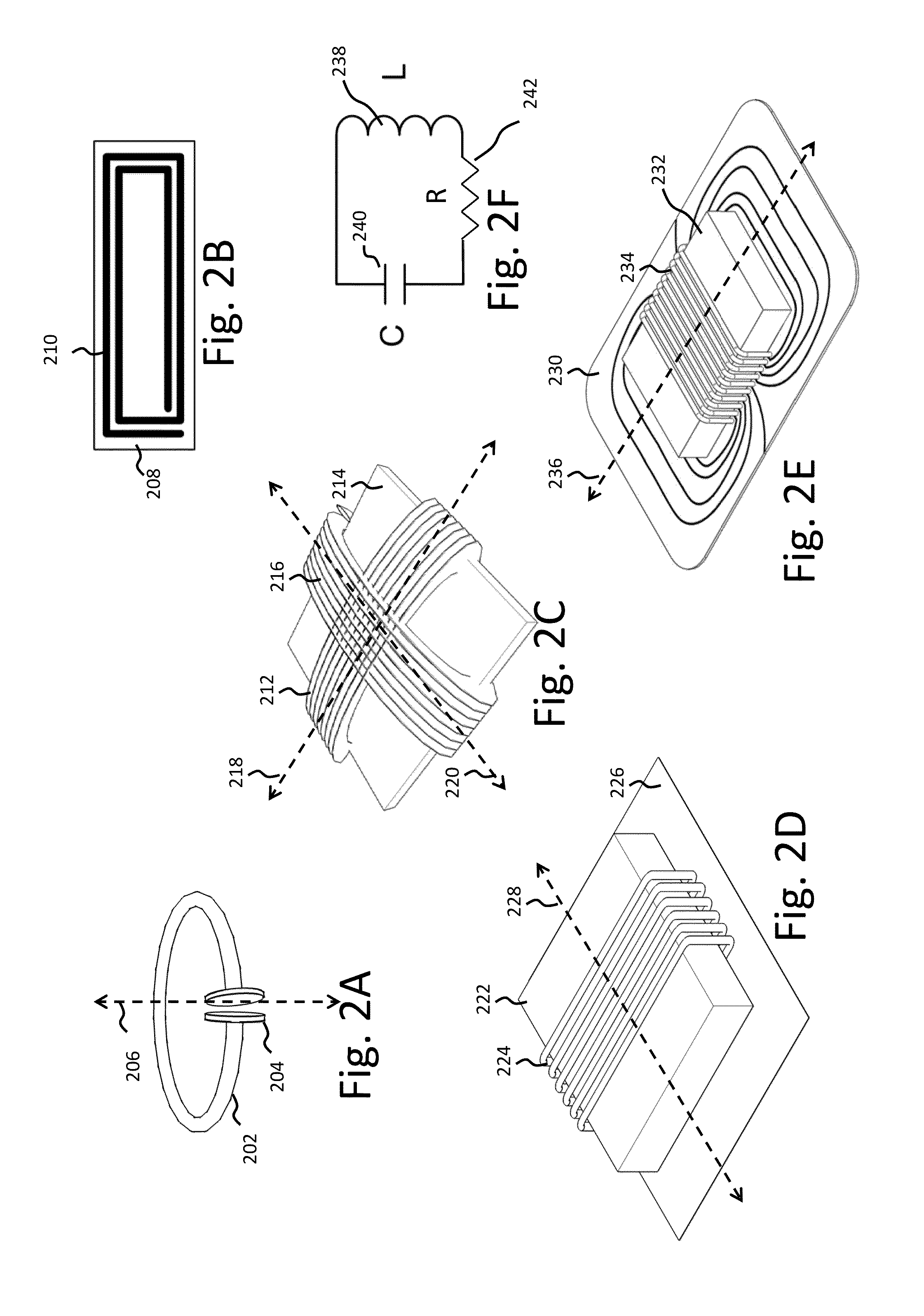
[0105]As those skilled in the art will recognize, important considerations for resonator-based power transfer include resonator efficiency and resonator coupling. Extensive discussion of such issues, e.g., coupled mode theory (CMT), coupling coefficients and factors, quality factors (also referred to as Q-factors), and impedance matching is provided, for example, in U.S. patent application Ser. No. 12 / 789,611 published on Sep. 23, 2010 as US 20100237709 and entitled “RESONATOR ARRAYS FOR WIRELESS ENERGY TRANSFER,” and U.S. patent application Ser. No. 12 / 722,050 published on Jul. 22, 2010 as US 20100181843 and entitled “WIRELESS ENERGY T...


PUM

PropertyMeasurementUnit
resonant frequenciesaaaaaaaaaa
poweraaaaaaaaaa

Abstract

Described herein are improved configurations for a wireless power transfer involving photovoltaic panels. Described are methods and designs that use electric energy from a photovoltaic module to energize at least one wireless energy source to produce an oscillating magnetic field for wireless energy transfer. The source may be configured and tuned to present an impedance to a photovoltaic module wherein said impedance enables substantial extraction of energy from said photovoltaic module.

Description

CROSS-REFERENCE TO RELATED APPLICATIONS[0001]This application claims the benefit of U.S. Provisional patent application 61 / 523,998 filed Aug. 16, 2011.[0002]This application is a continuation-in-part of U.S. Ser. No. 13 / 232,868 filed Sep. 14, 2011.[0003]This application is a continuation-in-part of U.S. Ser. No. 12 / 899,281 filed Oct. 6, 2010.[0004]This application is a continuation-in-part of U.S. Ser. No. 12 / 860,375 filed Oct. 20, 2010.[0005]This application is a continuation-in-part of U.S. Ser. No. 12 / 722,050 filed Mar. 11, 2010.[0006]This application is a continuation-in-part of U.S. Ser. No. 12 / 612,880 filed Nov. 5, 2009.[0007]The Ser. No. 12 / 722,050 application is a continuation-in-part of U.S. Ser. No. 12 / 698,523 filed Feb. 2, 2010 which claims the benefit of U.S. Provisional patent application 61 / 254,559 filed Oct. 23, 2009. The Ser. No. 12 / 698,523 application is a continuation-in-part of U.S. Ser. No. 12 / 567,716 filed Sep. 25, 2009.[0008]The Ser. No. 12 / 612,880 application ...

Claims


Application Information

Patent Timeline
Patent Type & Authority Patents(United States)
IPC IPC(8): H01F27/42H01F37/00H01F38/00B60L3/00B60L11/18H01F38/14H02J3/38H02J5/00H03H7/40H04B5/00
CPCH01F38/14B60L3/0069B60L11/182B60L11/184B60L11/1842B60L11/1844B60L11/1846H02J3/383H02J5/005H03H7/40H04B5/0037H04B5/0081B60L2200/12B60L2200/22B60L2210/10B60L2210/20B60L2210/30B60L2210/40B60L2230/22B60L2230/24B60L2250/10B60L2250/16B60L2260/28Y02T10/7005Y02T10/7241Y02T10/7094Y02T10/7216Y02T10/725Y02T90/163Y02T90/169Y02T90/14Y02T90/128Y02T90/127Y02T90/122Y02E10/563Y04S10/126Y04S30/14Y02E60/721B60L53/64B60L55/00B60L53/63B60L53/65B60L53/51B60L53/52H02J50/12H02J7/35B60L53/122B60L53/126B60L53/124H02J2300/24H02J3/381Y02B10/10Y02E10/56Y02E60/00Y02T10/7072Y02T10/72Y02T90/12Y02T90/167Y02T10/70H02J50/70H02J50/90H02J50/80Y02T90/16
Inventor KESLER, MORRIS P.HALL, KATHERINE L.GILER, ERIC R.KULIKOWSKI, KONRAD J.CAMPANELLA, ANDREW J.VERGHESE, SIMON
Owner WITRICITY CORP
Why Eureka
Eureka Blog
Learn More