Frequency-scanning interferometer with non-specular reference surface

a frequency-scanning interferometer and reference surface technology, applied in the direction of instruments, measurement devices, using optical means, etc., can solve the problems of reducing the accuracy of measurement step sizes, reducing the cost and complexity of frequency-scanning interferometers, and reducing aperture dimensions

Inactive Publication Date: 2006-06-06
LIGHTGAGE
View PDF22 Cites 22 Cited by
  • Summary
  • Abstract
  • Description
  • Claims
  • Application Information

AI Technical Summary

Benefits of technology

[0020]The non-specular property of the reflective reference surface can also be defined as a form of dispersion, which can be structured or unstructured. For example, the non-specular or dispersion properties of the reference surface can produce a random or an ordered alteration of the reference beam. Preferably, the alteration is largely random causing the rays of the reference beam to scatter upon reflection from the reference surface. However, the alteration can include beam-shaping properties for such purposes as controlling and distributing beam contents within a prescribed form. The random component of the alteration of the reference beam can be characterized as reducing spatial coherence or as reducing anisotropic reflection.
[0025]The invention can significantly reduce the cost and complexity of frequency-scanning interferometers by making a fundamental modification to the form of the reference surface used in the interferometer. A recognition of the attendant changes made possible by the modified reference surface is also required to fully exploit the invention. For example, the recognition should include an appreciation that a non-specular or diffuse reference surface is capable of making a representative portion of an otherwise expanding reference beam available to an imaging system at a reduced aperture dimension.
[0028]Preferably, the diffuse surface produces a largely random alteration of the reference beam. For example, the diffuse surface can be arranged for scattering the reference beam throughout a range of different directions and thereby reduce anisotropic reflection of the reference beam. However, the diffuse surface can include beam-shaping structures that produce an at least partially ordered alteration of the reference beam. For example, such beam-shaping structures can be used to alter a distribution of beam components within the reference beam.
[0033]Preferably, the non-specular reflection produces a largely random alteration of the reference beam. For example, the non-specular reflection can scatter the reference beam throughout a range of different directions and thereby reduce anisotropic reflection of the reference beam. Alternatively, the non-specular reflection can produce an at least partially ordered alteration of the reference beam.

Problems solved by technology

The illuminating systems generally employ expensive collimating optics so that individual rays of the object and reference beams approach the object and reference surfaces at normal incidence or at least at a constant angle of incidence.
Differences between the object and reference surfaces measured as path length variations between the object and reference beams are generally attributed to errors in the object surface.
Interference patterns produced by overlapping images of the object and reference surfaces contain fringe patterns of constructive and destructive interference between the object and reference beams.
Second, only object surfaces having limited roughness can be unambiguously measured.
Conventional interferometers are typically limited to measuring step sizes in the direction of illumination within the fringe spacing of their interference patterns, which relate directly to the wavelength of the illumination.
The cost of such optical systems becomes prohibitively expensive for measuring large test objects and can remain considerable even for measuring small test objects.
Collimating optics, especially those sized for measuring large test objects are particularly expensive and occupy considerable space, which are detrimental to making more compact interferometer systems.

Method used


Image

  • Frequency-scanning interferometer with non-specular reference surface
  • Frequency-scanning interferometer with non-specular reference surface
  • Frequency-scanning interferometer with non-specular reference surface

Examples


Embodiment Construction

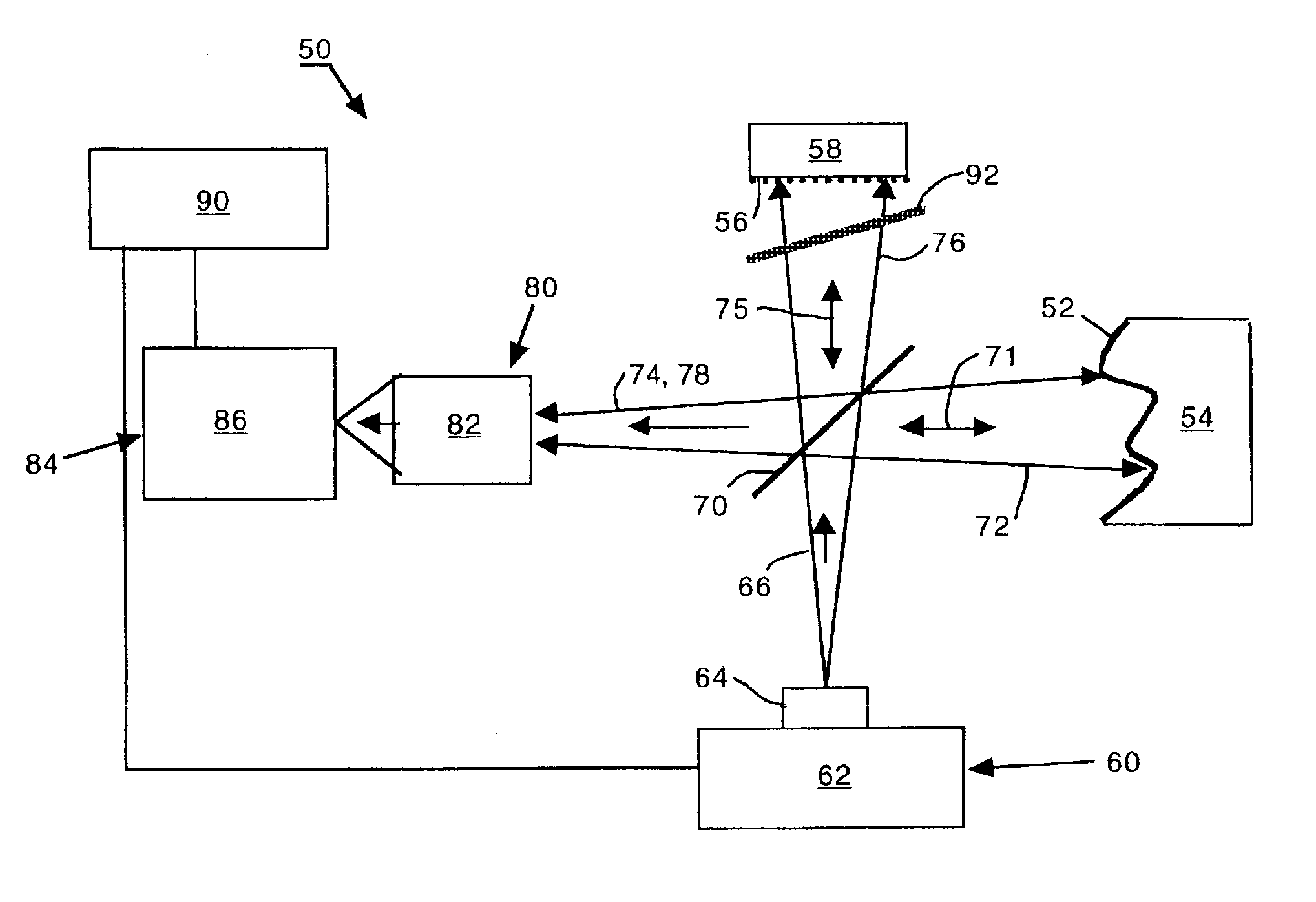
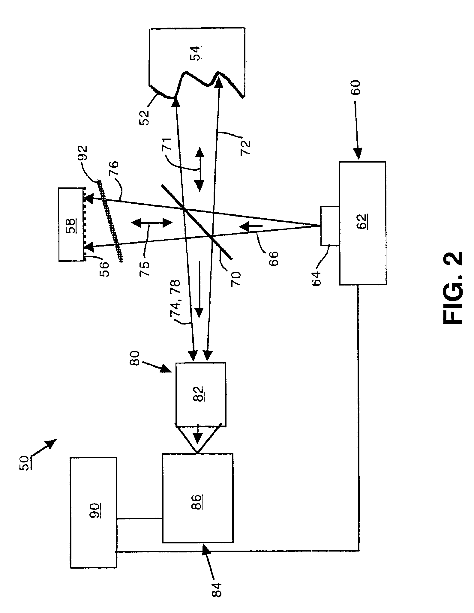
[0042]An embodiment of the invention as a modified frequency-scanning interferometer 50 arranged for measuring a diffuse object surface 52 is shown in FIG. 2. The frequency-scanning interferometer 50 is configured generally as a Twyman-Green interferometer, but other known interferometer configurations could also be used. However, unlike conventional Twyman-Green interferometers, no collimating optics are employed and a reference surface 56 is arranged as a non-specular or diffuse surface.

[0043]A radiation source 62 associated with an illuminating system 60 produces an expanding measuring beam 66. Beam conditioning optics 64 control expansion of the measuring beam 66 to fill corresponding aperture dimensions of the object surface 52 and the reference surface 56. Preferably, the radiation source 62 is a point source of coherent radiation, such as a diode laser (e.g., a GaAs-based laser), tunable through a limited range of frequencies (or wavelengths). The expanding measuring beam 66 ...


PUM


Abstract

A frequency-scanning interferometer is modified to include a diffuse reference surface. An illuminating system produces an expanding measuring beam, portions of which reflect from a test object surface and the diffuse reference surface on converging paths to an imaging system. Interference patterns between overlapping images of the object and reference surfaces are generated at a plurality of frequencies for measuring the object surface with respect to the reference surface.

Description

RELATED APPLICATIONS[0001]This application claims the benefit of prior filed U.S. Provisional Application No. 60 / 392,810, filed Jul. 1, 2002, which is hereby incorporated by reference.TECHNICAL FIELD[0002]Frequency-scanning interferometry exploits relationships between interference and beam frequency to measure path length differences between interfering object and reference beams.BACKGROUND[0003]Conventional interferometers arranged for comparing object and reference surfaces using the mechanism of interference generally require illuminating and imaging systems that are matched in size to the size of the object surface. Typically, the illuminating systems collimate the object and reference beams at a common diameter encompassing the desired measurement area of the object surface. Imaging systems collect the collimated object and reference beams following respective reflections from object and reference surfaces.[0004]Generally, the sizes of the object and reference beams are not si...

Claims


Application Information

Patent Timeline
Patent Type & Authority Patents(United States)
IPC IPC(8): G01B11/02G01B9/02
CPCG01B9/02078G01B9/02004
Inventor MARRON, JOSEPH C.FAKLIS, DEAN
Owner LIGHTGAGE
Why Eureka
Try Eureka