Speckle reduction apparatus based on Mie scattering, perturbation drive, and optical reflective chamber

a technology of optical reflection and speckle reduction, applied in lighting and heating apparatus, lighting device details, instruments, etc., can solve the problems of easy damage, large amount of optical energy, and large so as to reduce the spatial coherence of the incident laser, reduce the amount of mie scattering, and reduce the effect of speckles

Active Publication Date: 2018-09-18
SHANXI OVISION OPTRONICS CO LTD
View PDF18 Cites 0 Cited by
  • Summary
  • Abstract
  • Description
  • Claims
  • Application Information

AI Technical Summary

Benefits of technology

[0004]To overcome the drawbacks in the conventional methods for speckle reduction, such as ineffective, complex structure, easily damaged, high cost and so on, the present invention intends to provide a speckle reduction apparatus based on Mie scattering and perturbation drive.
[0010]Compared with the conventional technologies, an optical reflective chamber having transparent material provided therein is used in the present invention. Medium particles dispersed in the transparent material may induce Mie scattering of an incident laser and then the scattered light is split. The present invention further provides a perturbation-sensitive device, so that the external perturbations may cause the continuous changes of the incident states of the laser beam incident into the optical reflective chamber, and propagating directions as well as paths of the scattered light beams in the optical reflective chamber will be changed randomly. As a result, the spatial coherence of the incident laser may be reduced and the exiting scattered light from the exiting face of the optical reflective chamber are with different distributions of phase and scattering angle at different time, which is projected and generates the spatial distribution of a speckle image changing randomly. A plurality of speckle images may be superposed during integration time of human eye, which results in an image with uniform distribution of optical energy, and thus the speckles may be reduced effectively. By the experiments, the speckle contrast of the image may be lower than 4% with application of the apparatus of the present invention. As shown in FIG. 5, the speckle contrast of the image is 3.98%, which exhibits an extremely good speckle reduction. And, the external micrometer-scale perturbations are sufficient to trigger the perturbation-sensitive device. For example, vibrations from a fan of a general projector may meet the requirement of the perturbation magnitude and frequency to trigger the perturbation-sensitive device. Moreover, the effect of speckle reduction may be improved by increasing the intensities of the external perturbations or the concentration of the medium particles in the transparent material. In the present invention, the incident laser is “total-reflected” in the optical reflective chamber, and thus the total loss of the optical energy is minimized, so that a high efficiency of laser power is ensured and uniformity of the light is achieved during the process of “total-reflection”. In addition, the optical reflective chamber used in the present invention is common-designed without particular material required for the transparent material, and therefore it possesses the advantage of low cost.
[0011]The present invention may be implemented with reasonable and compact structure, achieving the following effects: low cost, effective speckle reduction, high laser efficiency, stability, safety, and uniform light intensity.

Problems solved by technology

When a screen is illuminated by coherent light such as laser, due to coherence of the laser and optical roughness of the screen surface, speckle noise pattern is observed by observer's eyes, which seriously affects the display quality of the image and covers useful information.
All the above methods require mechanical vibration, even the high-frequency or large amplitude vibration, or require integration of multiple light sources, with the disadvantages of complex structure, easy to damage, high cost not only, but also speckle reduction being ineffective.

Method used


Image

  • Speckle reduction apparatus based on Mie scattering, perturbation drive, and optical reflective chamber
  • Speckle reduction apparatus based on Mie scattering, perturbation drive, and optical reflective chamber
  • Speckle reduction apparatus based on Mie scattering, perturbation drive, and optical reflective chamber

Examples


Embodiment Construction

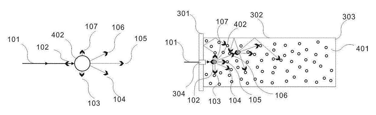
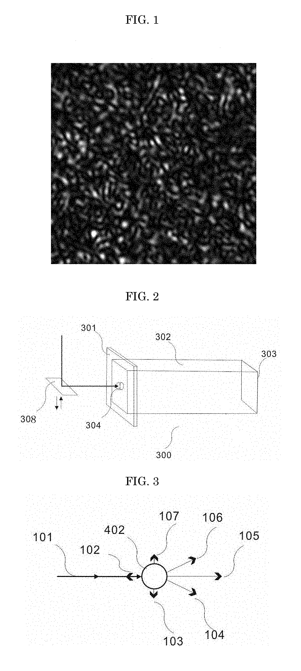
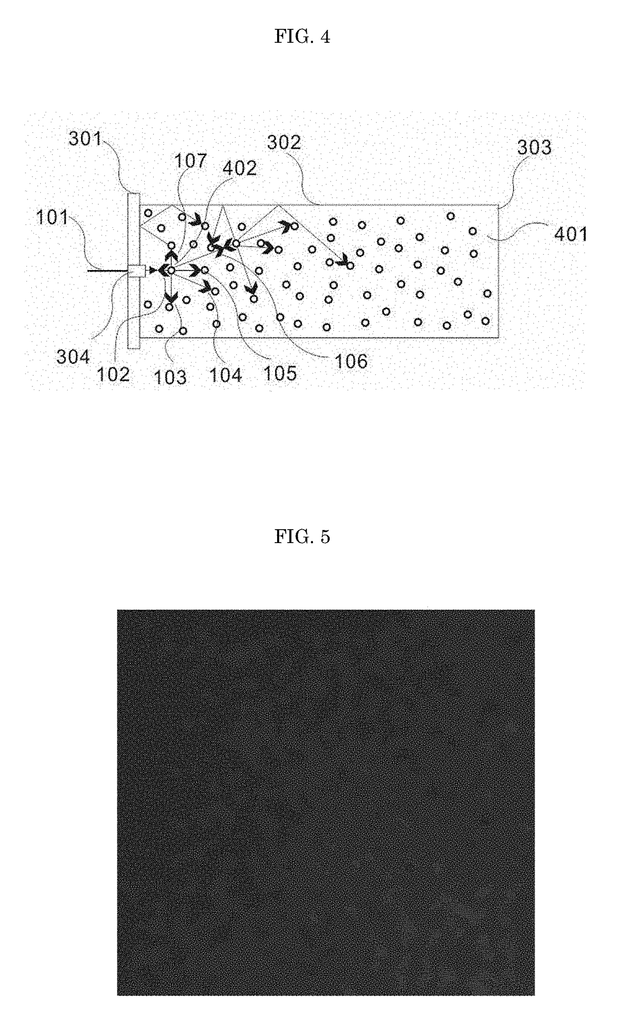
[0047]As shown in FIG. 2, a speckle reduction apparatus based on Mie scattering and perturbation drive comprises an optical reflective chamber 302 having an incident-light coupling device 301 and a light transparent exiting face 303 disposed thereon, and an optical device 308 for directing the laser incidence into the optical reflective chamber 302, wherein the optical means 308 is facing the incident-light coupling device 301 of the optical reflective chamber 302; wherein the inner walls of the optical reflective chamber 302, except for the wall of light transparent exiting face 303, are “mirror” surfaces (i.e., the inner walls having a high reflective property, which can “total-reflect” the incident laser beam into the optical reflective chamber 302), and the optical reflective chamber 302 is filled fully with transparent material 401 having medium particles 402 dispersed therein, dimensions of which are able to induce Mie scattering of the incident laser; wherein either or both o...


PUM

PropertyMeasurementUnit
lengthaaaaaaaaaa
integration timeaaaaaaaaaa
Mie scatteringaaaaaaaaaa

Abstract

A speckle reduction apparatus (300) based on Mie scattering and perturbation drive is disclosed. The speckle reduction apparatus (300) comprises an optical reflective chamber (302) having an incident-light coupling device (301) and an exiting face (303) disposed thereon, and an optical device (308) which faces the incident-light coupling device (301) of the optical reflective chamber (302). The inner walls of the optical reflective chamber (302), except for the wall of light transparent exiting face (303), are mirror surfaces. The optical reflective chamber (302) is fully filled with transparent material (401) having medium particles (402) dispersed therein, which are able to induce Mie scattering of the incident laser. Either or both of the optical reflective chamber (302) and the optical device (308) are provided with a perturbation-sensitive device. The present invention may be implemented with reasonable and compact structure, achieving the following effects: low cost, effective speckle reduction, high laser efficiency, stability, safety, and uniform light intensity.

Description

FIELD OF THE INVENTION[0001]The present invention relates to the field of display technology having a coherent light source, in particular to a speckle reduction apparatus based on Mie scattering and perturbation (generally, referring to micro-vibration) drive, mainly for the phenomenon of the optical speckles in the laser display technology and the optical instruments.BACKGROUND OF THE INVENTION[0002]When a screen is illuminated by coherent light such as laser, due to coherence of the laser and optical roughness of the screen surface, speckle noise pattern is observed by observer's eyes, which seriously affects the display quality of the image and covers useful information. Therefore, how to reduce the speckles has been a research hotspot in the fields of optical instruments and display technologies. In view of the current research, many methods used to reduce speckle have been developed, which roughly can be classified as the following: i) Controlling the coherence time of the las...

Claims


Application Information

Patent Timeline
Patent Type & Authority Patents(United States)
IPC IPC(8): G02B27/48G02B5/02F21V7/00G02F1/1335G03H1/32
CPCG02B27/48G02B5/0242F21V7/0091G02B5/02G02B5/0205G02B5/0236G02F1/133606G03H1/32
Inventor CHEN, XUYUANGAO, WENHONGSHI, YUNBOXU, MEIFANG
Owner SHANXI OVISION OPTRONICS CO LTD
Why Eureka
Try Eureka