
Beverage forming system having liquid delivery tank with expansion chamber

a technology of liquid delivery tank and expansion chamber, which is applied in the field of beverage forming system, can solve the problems of inability to deliver heated liquid from the tank, inability to deliver water from the brew chamber outlet, and inability to achieve precise volume of water

Active Publication Date: 2014-03-11
KEURIG GREEN MOUNTAIN INC
View PDF18 Cites 33 Cited by
  • Summary
  • Abstract
  • Description
  • Claims
  • Application Information

AI Technical Summary

Benefits of technology

[0005]Some aspects of the invention relate to arrangements for helping to prevent unwanted discharge of water or other liquid from a heater tank, e.g., due to expansion of the liquid in the tank during heating. This problem may be encountered with systems that deliver water from a heater tank by introducing additional water into the tank so as to force heated water to a brew chamber or other section to form a beverage. For example, in some systems, a heater tank may be full of heated water such that the hottest water is located near a top of the tank. To deliver heated water from the tank, cold water may be introduced at an inlet located near the bottom of the tank. The addition of cold water to the tank may displace heated water in the tank, causing the heated water to exit the tank, e.g., at an outlet near the top of the heater tank. This type of system can be very effective, and can deliver precise volumes of water, e.g., where the volume of cold water delivered to the heater tank can be closely controlled.
[0008]In one aspect of the invention, a beverage forming system that delivers heated liquid from a heater tank for discharge from the system by introducing liquid into the tank, e.g., to make a beverage, may operate to introduce air into the heater tank after liquid delivery is complete to evacuate a top portion of the tank of liquid and a conduit leading from a top of the tank to a brew chamber or other outlet. While systems like that in U.S. Pat. No. 7,398,726 introduce air into a heater tank to deliver heated water from the tank, such systems do not deliver heated liquid from the tank by introducing liquid into the tank. Also, in some embodiments in accordance with the invention, an outlet of the heater tank may be at an extreme top of the tank. Thus, by evacuating the top portion of to the tank of liquid, unwanted discharge of liquid from the tank may be made more effective.
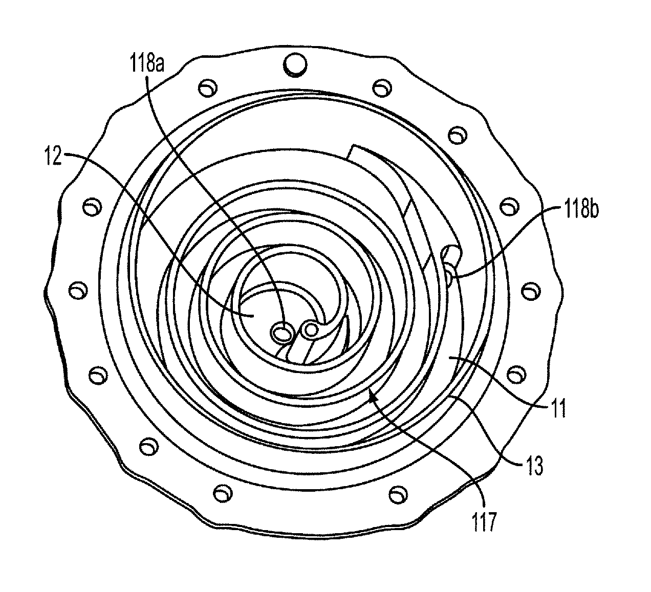
[0010]In one embodiment, an air inlet end of the expansion chamber flow path may be arranged to be lower than an outlet end of the flow path at the heater tank outlet. This arrangement may allow the expansion chamber to provide a well-controlled gas volume in the heater tank and / or help expel liquid from the expansion chamber and to the tank outlet during air purging of the expansion chamber. For example, by having the air inlet end positioned below the outlet end, air will tend to flow from the air inlet end toward the outlet end. This flow may help to at least partially evacuate the flow path as air flows from the air inlet end to the outlet end and displaces any liquid in the flow path. Also, any liquid in the tank will tend to enter the expansion chamber at the air inlet end rather than at the outlet end, e.g., because the liquid will tend to be heavier than air in the expansion chamber. As a result, any volume expansion of liquid will tend to initially enter the expansion chamber at the air inlet end, and subsequently flow toward the outlet end along the flow path with any further expansion. That is, liquid will tend to first fill (or at least partially or substantially fill) the expansion chamber before reaching the outlet of the heater tank. By providing the expansion chamber flow path with a desired volume, unwanted discharge of liquid from the tank due to thermal expansion can be resisted.
[0012]In some embodiments, an air pump may be arranged to introduce air into the air inlet for flow through the expansion chamber and to the outlet. Thus, the air pump may be operated after liquid delivery from the tank is complete (e.g., introduction of cool, unheated water into the heater tank is stopped), and may serve to not only to at least partially remove liquid from the expansion chamber, but also help to remove liquid from a conduit leading from the tank outlet to a brew chamber or other beverage outlet. Therefore, the air pump and the expansion chamber may be arranged such that air introduced into the air inlet at least partially evacuates a top of the heater tank of liquid. Also, some beverage forming systems may use a cartridge to hold a beverage medium used to make a beverage by mixing heated liquid with the beverage medium in the cartridge. Air introduced into the tank by the air pump may also help to expel beverage from the cartridge, e.g., to help reduce dripping of beverage from the cartridge after beverage formation is complete.
[0016]In another aspect of the invention, a method of forming a beverage includes heating liquid in the heater tank, providing a liquid to a heater tank via a liquid inlet, delivering liquid from the heater tank to a beverage medium to form a beverage via an outlet at a top of the heater tank, and introducing air into a tortuous flow path of an expansion chamber at the top of the heater tank after delivery of liquid to the heater tank is stopped to expel liquid from at least a portion of the expansion chamber. As discussed above, expelling liquid from at least a portion of an expansion chamber may help reduce or eliminate unwanted discharge of liquid from the heater tank, e.g., due to thermal expansion or other mechanisms, such as siphon-based flow.

Problems solved by technology

This problem may be encountered with systems that deliver water from a heater tank by introducing additional water into the tank so as to force heated water to a brew chamber or other section to form a beverage.
However, such systems can be susceptible to unwanted delivery of water from the heater tank due to thermal expansion.
This unwanted delivery can be manifested by dripping of water from a brew chamber or beverage / liquid outlet of the system after beverage formation is completed.
However, heating of the water will cause the water to expand, and if the heater tank has a fixed volume, this expansion may cause water to be delivered from the tank outlet to the brew chamber or other outlet.
As a result, water may undesirably drip from the brew chamber outlet during water heating even though no beverage is being formed.
This undesired liquid discharge may cause a mess, e.g., at a drip tray or other location where the liquid exits.
While systems like that in U.S. Pat. No. 7,398,726 introduce air into a heater tank to deliver heated water from the tank, such systems do not deliver heated liquid from the tank by introducing liquid into the tank.

Method used


Image

  • Beverage forming system having liquid delivery tank with expansion chamber
  • Beverage forming system having liquid delivery tank with expansion chamber
  • Beverage forming system having liquid delivery tank with expansion chamber

Examples


Embodiment Construction

[0027]It should be understood that aspects of the invention are described herein with reference to certain illustrative embodiment and the figures. The illustrative embodiments described herein are not necessarily intended to show all aspects of the invention, but rather are used to describe a few illustrative embodiments. Thus, aspects of the invention are not intended to be construed narrowly in view of the illustrative embodiments. In addition, it should be understood that aspects of the invention may be used alone or in any suitable combination with other aspects of the invention.

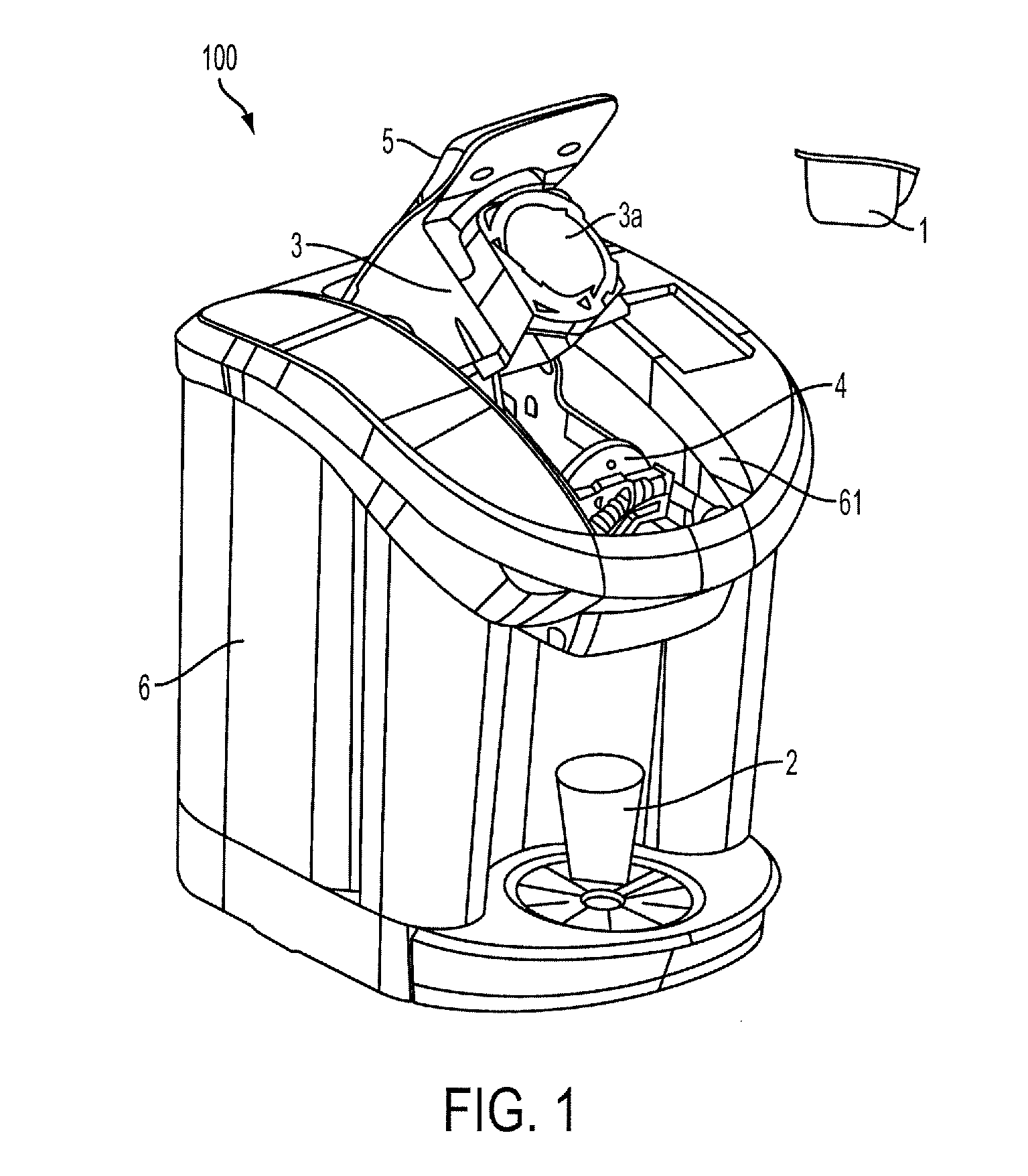
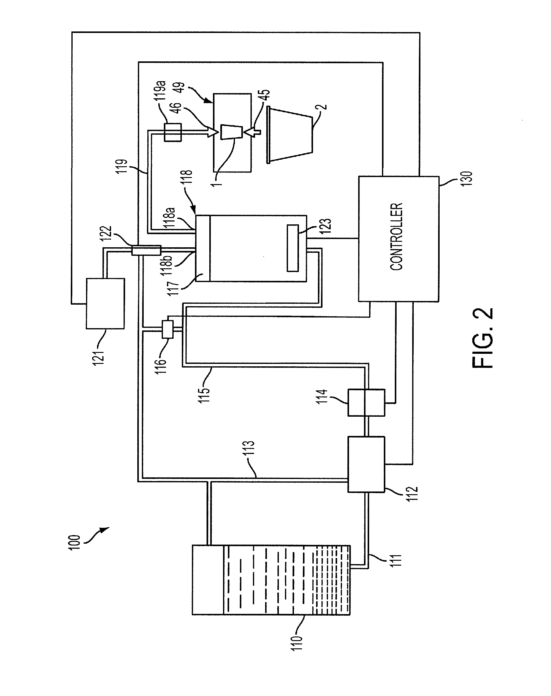
[0028]FIG. 1 shows a perspective view of a beverage forming system 100. Although the beverage forming system 100 may be used to form any suitable beverage, such as tea, coffee, other infusion-type beverages, beverages formed from a liquid or powdered concentrate, soups, juices or other beverages made from dried materials, or other, in this illustrative embodiment, the system 100 is arranged to form coff...


PUM


Abstract

A beverage forming method and system employing the introduction of air into the heater tank and / or an expansion chamber after liquid delivery is complete. An expansion chamber may be provided at the top of the heater tank and provide a tortuous flow path from an air inlet to the tank outlet.

Description

BACKGROUND[0001]1. Field of Invention[0002]This invention relates to beverage forming systems, such as coffee brewers that use a liquid to form a coffee beverage.[0003]2. Related Art[0004]Beverage forming systems that use a liquid, such as water, to form a beverage are well known. For example, U.S. Patent Application publication 2008 / 0134902 discloses a beverage forming system that heats water in a reservoir and pneumatically delivers the heated water to a brew chamber for making a coffee drink or other beverage. U.S. Pat. No. 7,398,726 discloses another beverage forming system that delivers heated water from a dispensing tank to a brew chamber by pneumatic forcing of the water from the metering tank. U.S. Patent Application publications 2009 / 0120299 and 2008 / 0092746, and U.S. Pat. Nos. 3,511,166, 3,958,502, 4,602,145 and 4,263,498 disclose other system types in which water in a heater tank or heat exchanger is forced to flow out of the tank and to a beverage making station by intro...

Claims


Application Information

Patent Timeline
Patent Type & Authority Patents(United States)
IPC IPC(8): A47J31/44
CPCA47J31/54A47J31/46A23F3/18A23F5/262A47J31/469
Inventor COMINELLI, TOMSHEPARD, JAMES E.VITELLA, THOMAS
Owner KEURIG GREEN MOUNTAIN INC
Learn More