Fluid dispenser with positive displacement pump

a technology of positive displacement and dispenser, which is applied in the direction of liquid spraying apparatus, spraying apparatus, coatings, etc., can solve the problems of substantial consumption of felt material, inability to simply apply clear primer, and limitations of other known systems, so as to achieve a relatively low pressure of dispensed fluid and improve material flow

Active Publication Date: 2009-08-18
SWAGELOK CO +1
View PDF16 Cites 27 Cited by
  • Summary
  • Abstract
  • Description
  • Claims
  • Application Information

AI Technical Summary

Benefits of technology

[0008]In accordance with one aspect of the invention, a fluid dispensing apparatus uses positive displacement of the fluid for accurate metering of the quantity of liquid applied to a surface. Positive displacement refers generally to the idea of having a metering volume that is filled and emptied so that each cycle corresponds to an accurate volume of material dispensed independent of viscosity. In one embodiment, a fluid dispensing system includes a positive displacement piston pump. The pressure of the dispensed fluid can be quite low, such as about one psi or less for example, providing a better flow of material from the dispenser to form a uniform and controlled application.
[0010]In accordance with another aspect of the invention, control of the fluid quantity dispensed is performed by using a variable speed function to drive a positive displacement function. In one embodiment, the drive function is realized in the form of a variable speed air motor that drives a positive displacement function that is realized in the form of a positive displacement pump. In still a further aspect of the invention, the use of a variable speed drive function with a positive displacement function facilitates the use of the dispensing apparatus with a robotic function that moves the dispensing apparatus across a surface with a predetermined dispense rate versus position profile.

Problems solved by technology

In order to be effective, however, the clear primer cannot be simply applied but must be applied with a rubbing action as well.
Although the above referenced systems are a significant advance in the art, they as well as other known systems have limitations.
This results in a substantial consumption of the felt material.
This can cause a loss of or diminished contact between the felt applicator and the frit, especially as the robotic arm passes around corners.
The drip and drag process can result in an uneven application, particularly of the more viscous black primer.
Additionally, since the primers are applied by pulsing a dispensing gun on and off, it can be difficult to control the amount of liquid material applied to the frit.

Method used


Image

  • Fluid dispenser with positive displacement pump
  • Fluid dispenser with positive displacement pump
  • Fluid dispenser with positive displacement pump

Examples


Embodiment Construction

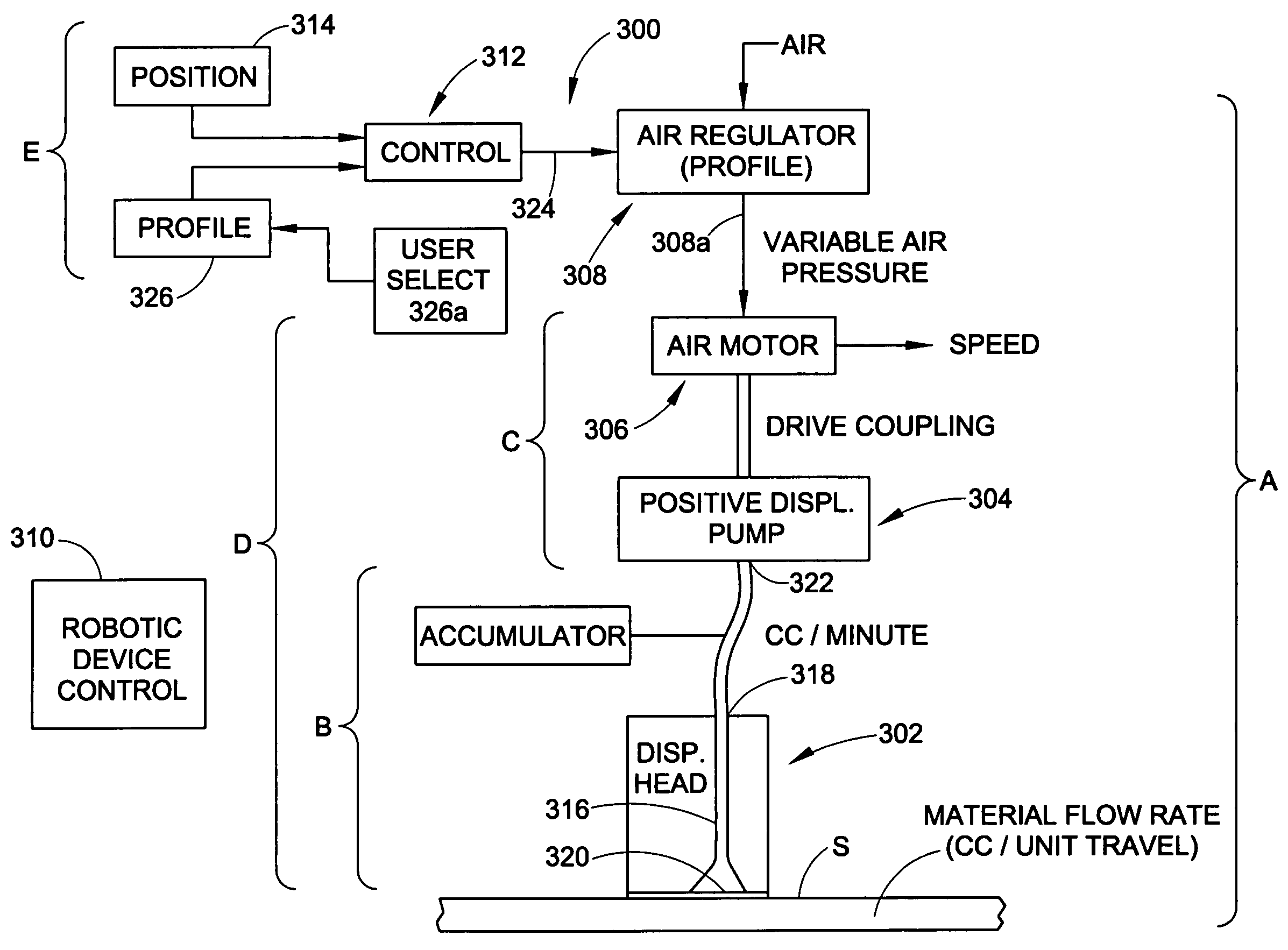
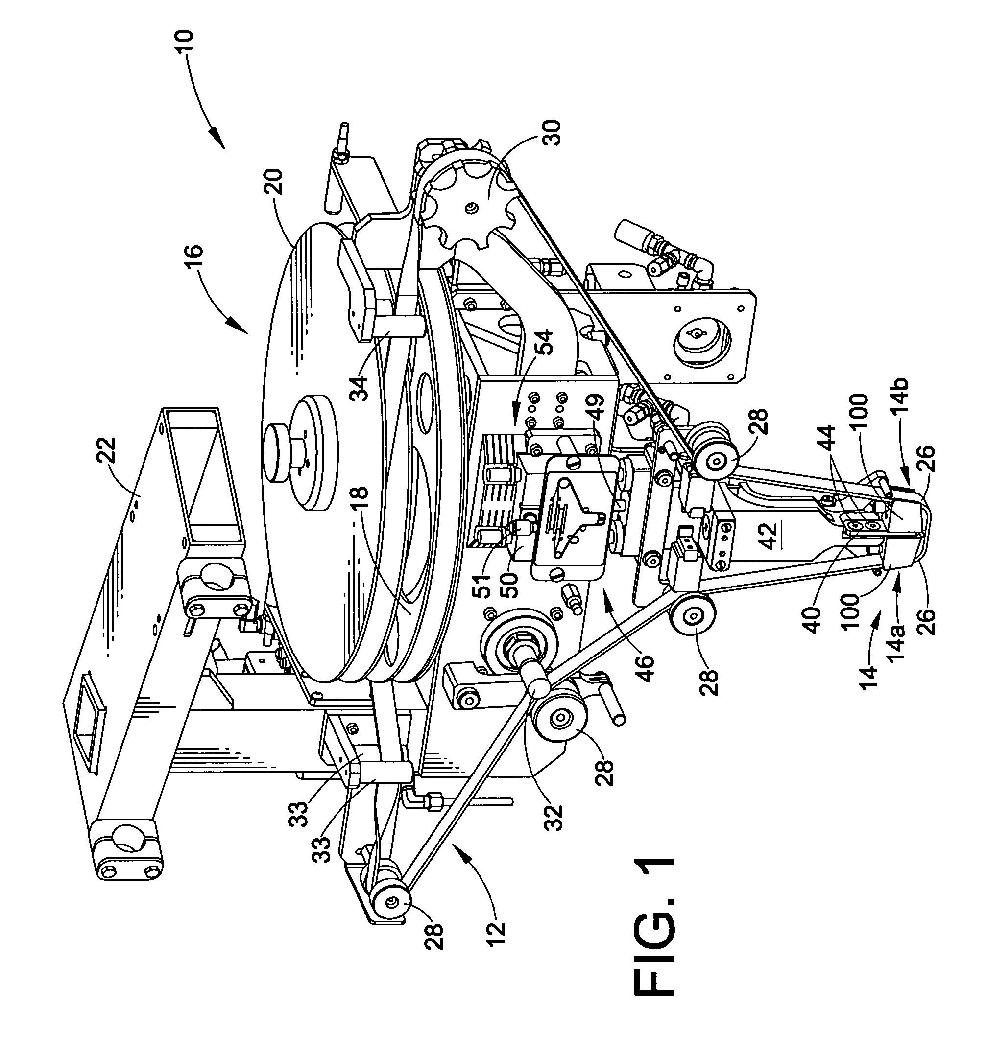
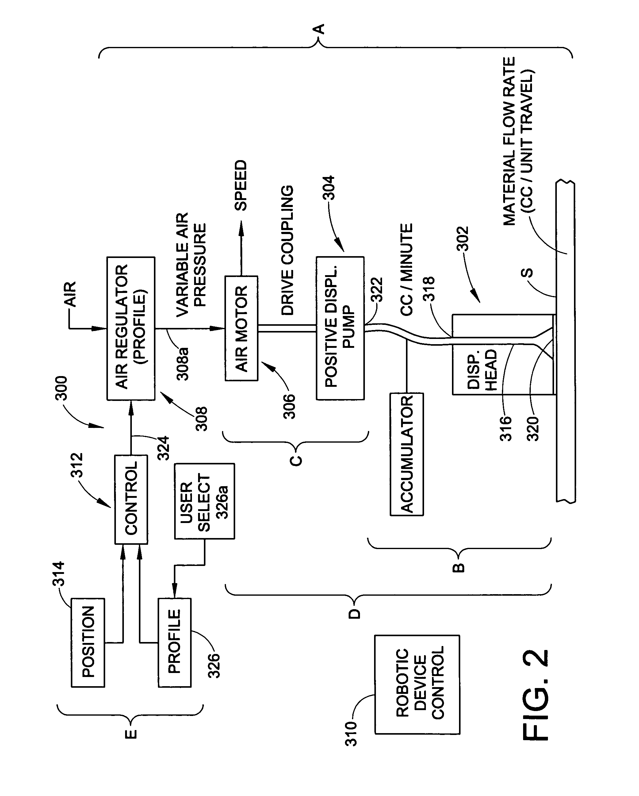
[0021]The present invention is directed to fluid dispensing apparatus for applying fluid to a surface. Although the invention is described herein with reference to a flow through felt dispenser, such as of the type described in the above-identified Wright et al patent, such descriptions are intended to be exemplary in nature and should not be construed in a limiting sense. Those skilled in the art will readily appreciate that various aspects of the invention may be used in different fluid dispensing apparatus without specific limitation as to the type of fluid, the surface, the design of the dispensing head and so on. For example, various functional and operational aspects of the invention are illustrated in an exemplary embodiment in FIG. 2 hereof without any particular limitation as to the structural dispenser features. The invention may find application to a flow through felt dispenser and applicator or a drip and drag type applicator to name two examples.

[0022]Many parts of the ...


PUM

PropertyMeasurementUnit
viscosityaaaaaaaaaa
viscosityaaaaaaaaaa
pressureaaaaaaaaaa

Abstract

Fluid dispensing apparatus uses positive displacement of the fluid for accurate metering of the quantity of liquid applied to a surface. Positive displacement includes a metering volume that is filled and emptied so that each cycle corresponds to an accurate volume of material dispensed independent of viscosity. In one embodiment, a positive displacement pump is used with a variable speed air motor. The air motor drives the pump. A variable output air regulator supplies air pressure to run the air motor based on a position signal. A profile may be used to relate position with motor speed and to control quantity to be dispensed.

Description

TECHNICAL FIELD OF THE INVENTION[0001]The invention relates generally to apparatus and methods for dispensing fluids onto a surface. More particularly, the invention provides a dispenser that utilizes positive displacement for the supply of fluid material to the dispenser head rather than pressure feed and additional features to provide a more uniform and consistent application to the surface.BACKGROUND OF THE INVENTION[0002]Many industries utilize dispensing systems to apply liquid material to a surface. In the motor vehicle industry, for example, liquid primers are applied to a perimeter region of a windshield as part of the process for installing a windshield in a vehicle body. These primers may be of various types and are preparatory to applying a urethane bead to the windshield that bonds the windshield to the frame. In a typical process, the windshield manufacturer applies a roughened black ceramic frit to a marginal or perimeter region of the windshield on the side of the gla...

Claims


Application Information

Patent Timeline
Patent Type & Authority Patents(United States)
IPC IPC(8): B05C1/06
CPCC03C17/002B05C11/10B05C1/14
Inventor ROMANIN, MARIO
Owner SWAGELOK CO
Why Eureka
Try Eureka