Precision dynamic measurement apparatus

a dynamic measurement and precision technology, applied in mechanical devices, liquid/fluent solid measurement, instruments, etc., can solve the problems of inaccurate force reading at high flow rate of some materials, and achieve the effect of high flow rate and higher f or force reading

Active Publication Date: 2012-10-30
BRANDT ROBERT O
View PDF16 Cites 8 Cited by
  • Summary
  • Abstract
  • Description
  • Claims
  • Application Information

AI Technical Summary

Benefits of technology

[0011]Generally, it has been found that the force reading becomes inaccurate at high flow rates of some materials due to the fact that the radius in the above formula, instead of being the surface of the pan, becomes the surface of the material being conveyed across the pan. As a result, the R denominator in the formula F=MV2 / R becomes smaller, resulting in a higher F or force reading.
[0012]In accordance with the present invention, it has been found that this deviation can be corrected without recalibration by decreasing the height of the discharge opening above the entry end of the pan as the flow increases. Decreasing the height results in a proportional decrease in the velocity of the material as the material travels across the pan. As a result, V for velocity in the above formula is decreased, resulting in a corresponding decrease in F to compensate for the smaller R.
[0013]It has also been found that this decrease in height with a corresponding increase in material flow rate can be accomplished through the use of a gate valve having an inclined gate member. The gate member is slidable across the valve opening or aperture between a closed position and an open position. As the gate member is moved toward the open position, the leading edge of the gate member moves away from the side of the aperture defined by the valve housing, increasing the size of the aperture opening or gap, thereby permitting an increased flow of material from the hopper or other supply source. At the same time, the height of the aperture opening, which is determined by the leading edge of the gate member is lowered. As a result, the material has a shorter distance to fall before reaching the pan upper edge, and thus moves across the pan at a lower velocity.
[0015]More specifically, when dispensing frangible particulate materials, such as cereals and potato chips, complete closure of the aperture will crush material caught between the valve housing and the gate member leading edge. When the aperture is again opened, the crushed particles are included in the material stream, diminishing the quality of the product.
[0016]By leaving the aperture slightly open, however, no crushing occurs. However, if the gap between the gate member leading edge and aperture wall is small, discharge of material will stop due to bridging of the material across the gap. Bridging, also known as arching or doming, is the characteristic of particulate materials to interlock when the particles are large relative to the opening, resulting in a bridge being formed across the gap due to the bonding between the particles. By utilizing this characteristic, normally considered to be a problem in dispensing of particulate materials, it is possible to effectively halt the flow of particulate material without damage to the material.
[0019]The valve includes a housing with a discharge opening or aperture defined by side walls, a slidable gate member having a closed position in which the aperture is completely or substantially closed, i.e., a small gap of predetermined width remains between the gate member leading edge and the aperture wall, and an open position in which the aperture is completely opened. The gate member is inclined so that the gate member leading edge moves downward as the aperture is opened, effectively lowering the position of the aperture relative to the measurement device. The valve also includes an actuator to control the position of the gate member.

Problems solved by technology

Generally, it has been found that the force reading becomes inaccurate at high flow rates of some materials due to the fact that the radius in the above formula, instead of being the surface of the pan, becomes the surface of the material being conveyed across the pan.

Method used


Image

  • Precision dynamic measurement apparatus
  • Precision dynamic measurement apparatus
  • Precision dynamic measurement apparatus

Examples


Embodiment Construction

[0028]In the following description, terms such as horizontal, upright, vertical, above, below, beneath, and the like, are used solely for the purpose of clarity in illustrating the invention, and should not be taken as words of limitation. The drawings are for the purpose of illustrating the invention and are not intended to be to scale.

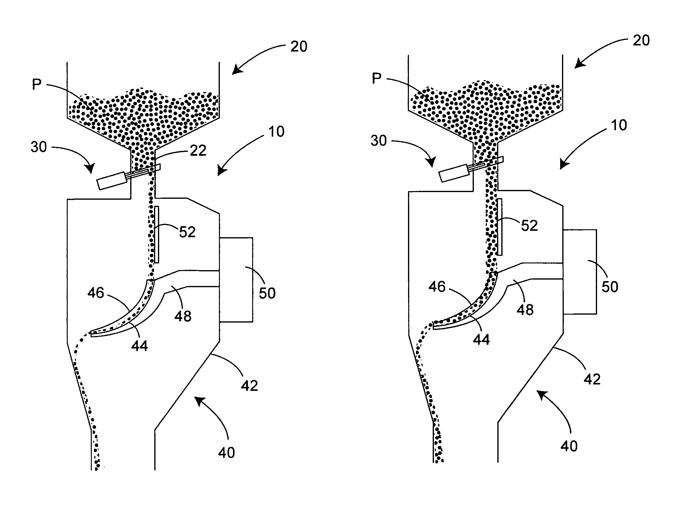
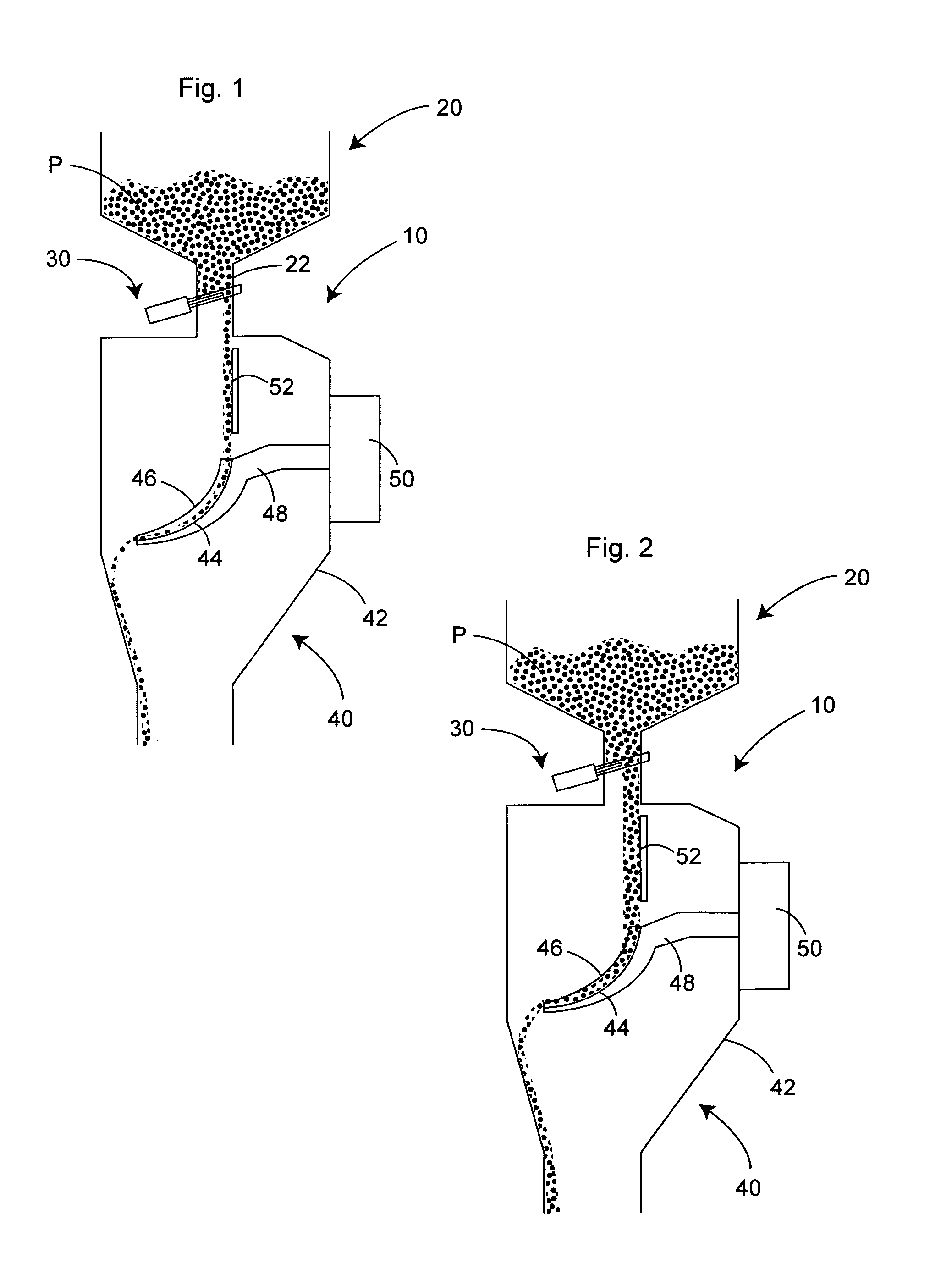
[0029]As best illustrated in FIGS. 1 and 2, the dispensing apparatus, generally 10, of the present invention is comprised of a hopper 20 having a discharge conduit 22, a gate valve 30 in communication with discharge conduit 22, and a dynamic measurement device, generally 40.

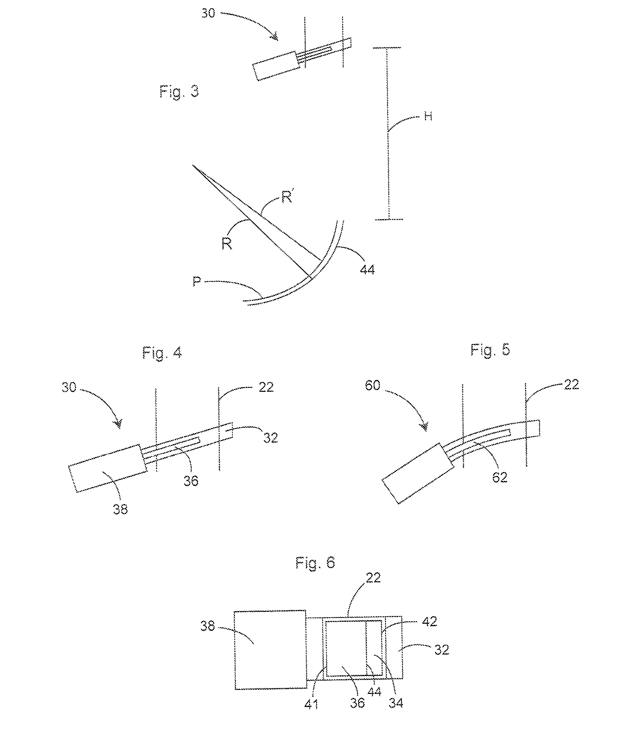
[0030]Valve 30 is comprised of a housing 32 having an aperture 34, a gate member 36, and a valve actuator 38 to position gate member 36 at selected positions across aperture 34. Aperture 34 includes rear and front walls, 41 and 42 respectively. Gate member 36 is inclined upwardly toward front wall 38. In most instances, the gate member will be inclined at an angle of from about 1°...


PUM


Abstract

A method and apparatus are described for accurately measuring the weight of a moving stream of particulate material at different flow volumes. The apparatus includes a dynamic measurement device with a deflectable curved pan for measuring the amount of material flowing along a pathway; a supply source for discharging material along the pathway; and a gate valve having an inclined gate member with a leading edge controlling the volume of material discharged from the supply source, the valve reducing the height of discharge of the material above the dynamic measurement device proportional to the increase in the flow volume of material being discharged. A gate valve is also described that includes a gate member with a fully open position and a fully closed position, the valve aperture being open a width determined by the bridging characteristics of the particulate material being discharged when the gate member is in the fully closed position.

Description

BACKGROUND OF THE INVENTION[0001](1) Field of the Invention[0002]The present invention relates to a method and apparatus for accurately measuring the weight of particulate material moving along a pathway at different flow rates, and in particular to a method and apparatus for precisely measuring the amount of particulate material moving along a pathway as the volume of material changes.[0003](2) Description of the Prior Art[0004]Numerous solid particulate materials are packaged in various types of containers for sale to the ultimate consumer or to a downstream processor. A brief exemplary listing of such materials include plastic and metal components and parts; food items, such as cereals, corn meal, rice, spices, soybeans, and potato chips; and a variety of other materials, such as tobacco, plastic pellets, etc.[0005]Generally, the material is fed as a continuous or discontinuous feed from a bulk supply source, such as a hopper, directly into the containers, intermediate collection...

Claims


Application Information

Patent Timeline
Patent Type & Authority Patents(United States)
IPC IPC(8): G01G13/18G01F1/30
CPCG01G9/00G01G11/003
Inventor BRANDT, ROBERT O.
Owner BRANDT ROBERT O
Why Eureka
Try Eureka