Opposing rib structure for non-round bottles

a rib structure and non-round bottle technology, applied in rigid containers, transportation and packaging, packaging, etc., can solve the problems of excessive material use and manufacturing, container weight increase, and difficulty in manufacturing, so as to improve the rib structure of vacuum label panel, improve dent resistance, and reduce the weight of the container

Active Publication Date: 2008-01-15
GRAHAM PACKAGING CO LP
View PDF12 Cites 11 Cited by
  • Summary
  • Abstract
  • Description
  • Claims
  • Application Information

AI Technical Summary

Benefits of technology

[0010]The present invention provides an improved blow molded non-round plastic container that has an improved vacuum label panel ribs. The design allows for improved dent resistance, reduces container weight and improves label panel support.
[0013]The present design solves these problems by combining an inward and outward rib design for the ribs positioned within the vacuum panel. The inward rib resists the bulge of the panel and improves bumper denting. The outward ribs add structure to the vacuum panel, label support and greater ease of material flow during inflation. This ease of material flow improves light weigh capability and broadens container design flexibility.
[0014]This design insures that the rectangular sides remain relatively flat which facilitates packing in box-shaped containers and the utilization of shelf when displayed in stores for retail sale. The containers are resistant to bellying out which renders them suitable for a variety of uses including hot-fill applications.
[0015]In hot-fill applications, the plastic container is filled with a liquid that is above room temperature and then sealed so that the cooling of the liquid creates a reduced volume in the container. The non-round hot-fill container of the present invention has four generally rectangular sides and a substantially rectangular base. It further comprises at least two vacuum panels located on two of the rectangular sides opposite one another. These panels have substantially curved upper and lower ends, as opposed to the substantially straight upper and lower ends. These vacuum panels also contain a series of ribs, which are parallel to each other and, preferably to the container base. These ribs have a rounded edge, which may point inward or outward relative to the interior of the container. At least one of these ribs, within each panel, has an inward edge. The remaining ribs within each panel have an outward edge. These panels and ribs are located opposite one another and, preferably each rib having an outward edge is opposite its counterpart in the opposite panel. Such a correlation enhances stability of the panel and, thereby the container.
[0017]The novel structure of the container of the invention, including the unique structure of the vacuum panels combined with novel reinforcement means, reduces the stress placed on the comers of the vacuum panels when the panels are flexed inwardly during filling and cooling and provide additional support to the panels to resist flexing and deformation due to sealing of the container. The inward and outward ribs of the container provide dent resistance to the panel and, as a result, to the container, and also permits the manufacture of containers having less weight. The inward outward rib sequence permits the a larger label panel surface area.
[0018]In addition, the novel design of the hot-fill container also provides for additional areas on the label mounting area for receiving an adhesive or for contact with a shrink wrap label, thereby improving the process for applying a label to the container.

Problems solved by technology

Such a design in a non-round container with a vacuum panel on the short axis of inflation detracts from the appearance of the container, causes structural problems, excessive material use and manufacturing difficulties.
Manufacturing difficulties are caused by freeze off of material earlier in the molding process.
This interferes with the efficient distribution of material in the container and causes containers to be heavier to compensate for the inefficient distribution of materials.
While an all outward rib design would eliminate early contact and provide more label surface area support, it causes the vacuum panel to bulge or belly outward when the label panel bumper is contracted and forced inward by vacuum.
This has the natural consequence of leaving the container prone to denting.

Method used


Image

  • Opposing rib structure for non-round bottles
  • Opposing rib structure for non-round bottles
  • Opposing rib structure for non-round bottles

Examples


Embodiment Construction

[0027]Embodiments of the invention are discussed in detail below. In describing embodiments, specific terminology is employed for the sake of clarity. However, the invention is not intended to be limited to the specific terminology so selected. While specific exemplary embodiments are discussed, it should be understood that this is done for illustration purposes only. A person skilled in the relevant art will recognize that other components and configurations can be used without parting from the spirit and scope of the invention. All references cited herein are incorporated by reference as if each had been individually incorporated.

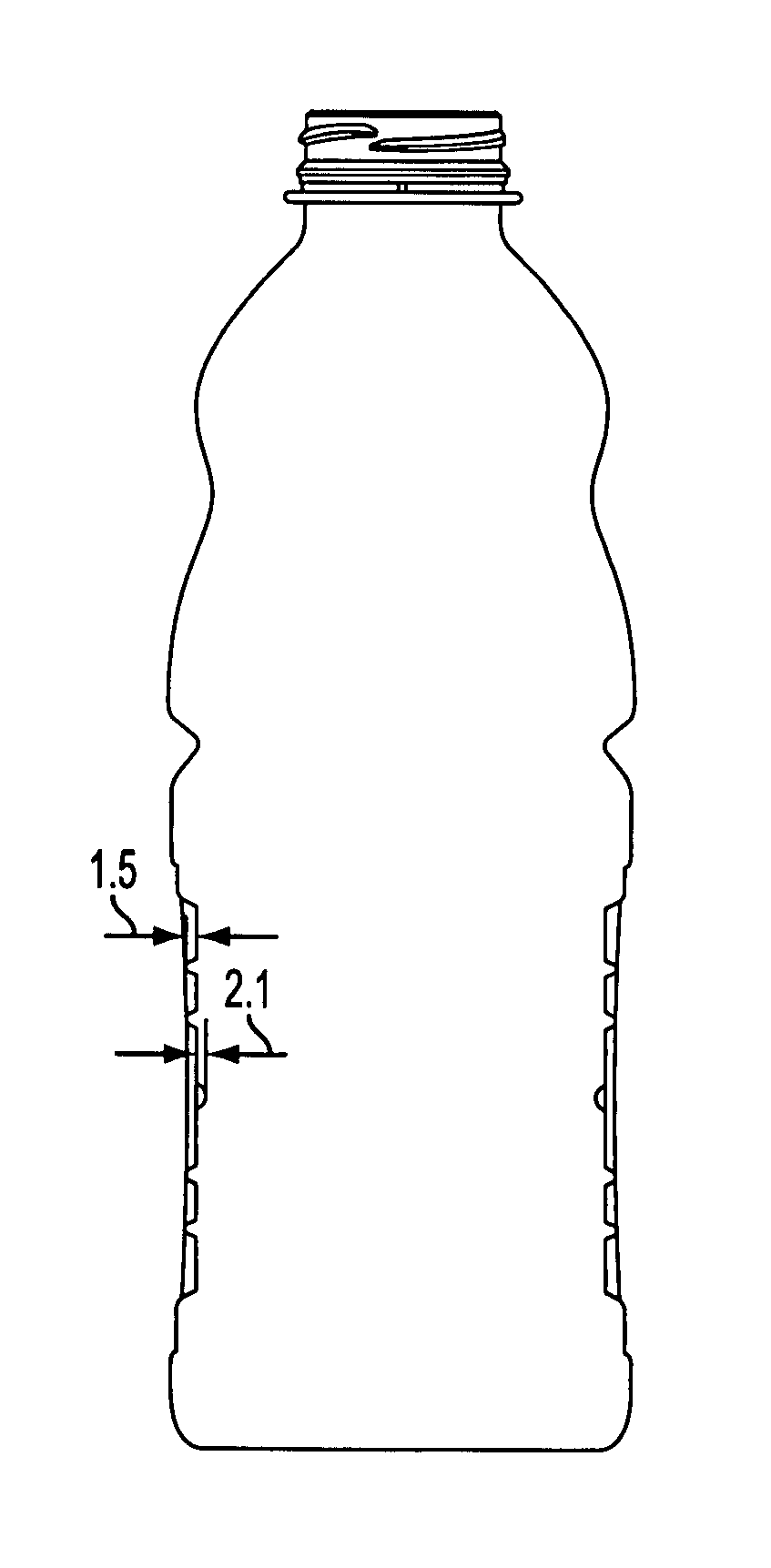
[0028]A thin-walled container in accordance with the present invention is intended to be filled with a liquid at a temperature above room temperature. According to the invention, a container may be formed from a plastic material such as polyethylene terephthalate (PET) or polyester. Preferably, the container is blow molded. The container can be filled by ...


PUM

PropertyMeasurementUnit
vertical lengthaaaaaaaaaa

Abstract

An improved blow molded plastic non-round container having rectangular sidewalls is adapted for hot-fill applications. The hot-fill container has vacuum panel reinforcement panels with rib structures located in a label mounting area on the sidewalls. In each panel, the ribs extend across the panel and are parallel to each other where the edge of one rib faces in each array faces inward and the others in the array face outward. The inward rib resists the bulge of the panel and improves bumper denting, ease of manufacture and light weigh capability.

Description

CROSS-REFERENCE TO RELATED APPLICATIONS[0001]This application claims priority under 35 U.S.C. § 119(e)(1) of provisional applications No. 60 / 398,022, filed Jul. 24, 2002 and 60 / 417,656, filed Oct. 11, 2002.BACKGROUND OF THE INVENTION[0002]1. Field of the Invention[0003]The present invention relates generally to blow-molded hot-fillable containers, and more particularly to hot-fillable containers having collapse panels.[0004]2. Related Art[0005]The use of blow molded plastic containers for packaging “hot-fill” beverages is well known. However, a container that is used for hot-fill applications is subject to additional mechanical stresses on the container that result in the container being more likely to fail during storage or handling. For example, it has been found that the thin sidewalls of the container deform or collapse as the container is being filled with hot fluids. In addition, the rigidity of the container decreases immediately after the hot-fill liquid is introduced into t...

Claims


Application Information

Patent Timeline
Patent Type & Authority Patents(United States)
IPC IPC(8): B65D90/02B65D1/02
CPCB65D1/0223B65D1/0276B65D2203/02B65D2501/0036B65D2501/0081B29C49/6605
Inventor KELLEY, PAUL V.
Owner GRAHAM PACKAGING CO LP
Why Eureka
Try Eureka