
Heated rotary drum and image forming device using said heated rotary drum

A technology for heating rollers and images, which is applied to the electric recording process using charge patterns, the equipment, shafts and bearings of the electric recording process applying charge patterns, etc. performance, reduced wear, improved deflection and sag resistance

Inactive Publication Date: 2006-05-03
FUJIFILM BUSINESS INNOVATION CORP
View PDF0 Cites 0 Cited by
  • Summary
  • Abstract
  • Description
  • Claims
  • Application Information

AI Technical Summary

Problems solved by technology

However, due to the poor lubricating performance in the initial use, the initial wear is large

Method used


Image

  • Heated rotary drum and image forming device using said heated rotary drum
  • Heated rotary drum and image forming device using said heated rotary drum
  • Heated rotary drum and image forming device using said heated rotary drum

Examples


Embodiment Construction

[0013] Embodiments of the present invention will be described below.

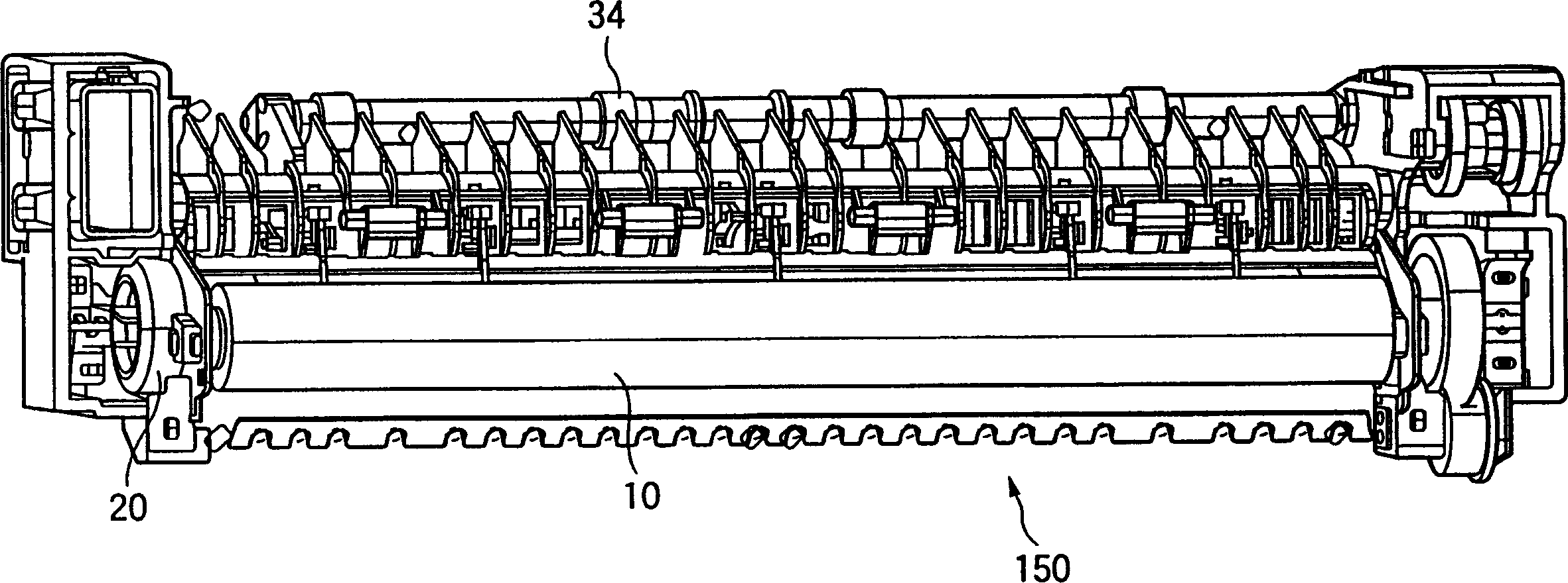
[0014] Figure 5 It is an overall explanatory diagram showing the image forming apparatus 100 to which the present invention is applied. Image forming apparatus 100 supplies static electricity from electrostatic roller 104 to photosensitive drum 102 to charge the photosensitive drum, and forms a latent image on photosensitive drum 102 by irradiating light such as laser light from exposure light unit 106 . The powder is supplied from the developing roller 110 of the developing device 18 to develop an image on the photosensitive drum 102 . The paper supplied through the paper supply path 128 passes between the photosensitive drum 102 and the transfer roller 112 to transfer an image onto the paper, and then the fixing roller 114 fixes the image on the paper. Paper is drawn from the paper cassette 120 through a paper supply path and advances over supply rollers 122,124. After being positioned on the registra...


PUM


Abstract

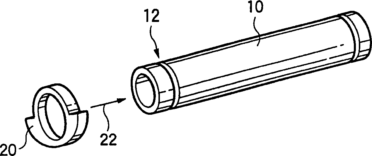
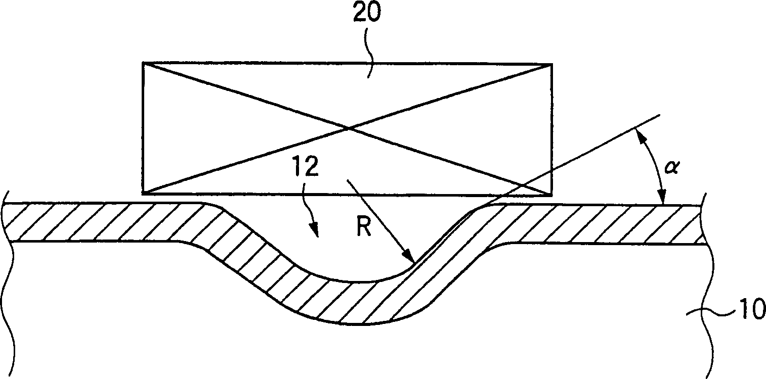
PURPOSE: To reinforce the abutting surface of the thinned heating roll of an image forming device on a bearing against deflection or dent, and also to reduce the initial wear of the bearing. CONSTITUTION: A circumferential groove 12 having a circular-arc shaped cross section whose radius is 1 to 3 mm is formed on the abutting surface of a fixing roll 10 on the bearing 20 by drawing cylindrical metal, and is used also as a lubricant holding part at the time of initially assembling the bearing.

Description

technical field [0001] The present invention relates to a heating roller and an image forming apparatus using the heating roller, and particularly relates to a structure of a support portion of the heating roller. Background technique [0002] The fixing device of the image forming apparatus is composed of a heating roller and a pressing roller, and is used to fix unfixed toner on the paper. For this fixing device, the heating roller is set to shorten the warm-up time when starting to work. The wall thickness of the cylinder should be as thin as possible. In the process of antirust treatment on the surface of the heating roller, the bottom layer is first coated, and then a fluororesin tube with a thickness of about 20 μm is put on it, and then the fluororesin tube is tightly adhered to the outer circumference of the cylinder through firing. Recently, in accordance with the above-mentioned thinning requirements, the wall thickness of the cylinder of ...

Claims


Application Information

Patent Timeline
Patent Type & Authority Patents(China)
IPC IPC(8): G03G15/20F16C13/00F16C13/02
CPCG03G15/2053G03G2215/20
Inventor 押田英夫田中康树实方启二难波仁之
Owner FUJIFILM BUSINESS INNOVATION CORP
Learn More