Apparatus And Method For Manufacturing Outer Race Member For Constant Velocity Joint And Intermediate Molded Body Of The Outer Race Member

a technology of constant velocity and outer race members, which is applied in the direction of mechanical apparatus, engine components, couplings, etc., can solve the problems of large upset in the releasing portion the total misalignment of the spline formed on the side of the first spline forming land, and it is not possible for a person skilled in the art to apply such a concept, etc., to achieve the effect of improving the durability of the die member, reducing load

Inactive Publication Date: 2008-05-29
HONDA MOTOR CO LTD
View PDF5 Cites 8 Cited by
  • Summary
  • Abstract
  • Description
  • Claims
  • Application Information

AI Technical Summary

Benefits of technology

[0023]It is a general object of the present invention to provide a method for manufacturing an outer race member for a constant-velocity universal joint, including a hole with further improved dimensional accuracy in a shank thereof.
[0024]The main object of the present invention is to provide a method for manufacturing an outer race member for a constant-velocity universal joint, wherein a reduced load is applied to a die member for forming the hole, thereby improving durability of the die member.
[0025]Another object of the present invention is to provide a method for manufacturing an outer race member for a constant-velocity universal joint, wherein a dimensionally precise hole is formed in a shank, with a reduced load being applied to a die member for forming the hole, so as to improve durability of the die member with favorable material flows when forging the shank with the hole, as well as to provide an intermediate formed body for manufacturing the outer race member for the constant-velocity universal joint.
[0026]According to the present invention, a workpiece loaded in a cavity of an upper die is pressed vertically downward by a first die member. A shank-forming portion of a lower die draws a shank, while a second die member positioned coaxially with respect to the first die member presses the shank. Thus, a primary formed body, having a hole in the shank, is formed. Because the shank with the hole is extruded prior to upsetting the primary formed body in a subsequent step to obtain a secondary formed body, improved product accuracy is achieved when the completed product is produced in the subsequent step, while also reducing the amount of finishing work performed with respect to the hole in the subsequent step.
[0027]Further, according to the present invention, a forming land, a releasing portion, and a correcting land are formed on an outer circumferential surface at one end of the second die member, such that the forming land and the correcting land are not directly connected, owing to the releasing portion being formed therebetween. In addition, according to the present invention, because the forming land of the second die member is positioned inside of an area between one end (F1) and the other end (F2) of the shank-forming portion that is formed in the lower die in a vertical direction, a material flow toward the shank caused by drawing the lower side of the workpiece through the shank-forming portion of the lower die, and another upward material flow caused by pressing the lower central portion of the workpiece through the second die member, can be suitably regulated.
[0028]As a result, according to the present invention, material is prevented from sticking to the outer surface of the second die member that forms the hole in the shank. Also, the load applied to the second die member is reduced, so as to improve durability of the second die member. A hole having improved dimensional accuracy (formational accuracy) can be formed in the shank as well.

Problems solved by technology

With this structure, a reaction force generated in the second spline forming land is focused on the releasing portions, located between the forming portions and the correcting portions of the first spline forming land, thereby causing a large upset in the releasing portions of the first spline forming land.
As a result, the splines formed on the side of the first spline forming land are totally misaligned.
Also, because the technical concept disclosed in Patent Document 4 relates to proposing an upper die, with the first spline forming land having forming portions and releasing portions thereon, and a lower die with the second spline forming land having forming portions, releasing portions and correcting portions thereon, it would not be possible for a person skilled in the art to apply such a concept to forming a hole in a female type shank of an outer race member.
In addition, heavy loads are applied to the dies, thus shortening the useful lifespan of the dies.

Method used


Image

  • Apparatus And Method For Manufacturing Outer Race Member For Constant Velocity Joint And Intermediate Molded Body Of The Outer Race Member
  • Apparatus And Method For Manufacturing Outer Race Member For Constant Velocity Joint And Intermediate Molded Body Of The Outer Race Member
  • Apparatus And Method For Manufacturing Outer Race Member For Constant Velocity Joint And Intermediate Molded Body Of The Outer Race Member

Examples


Embodiment Construction

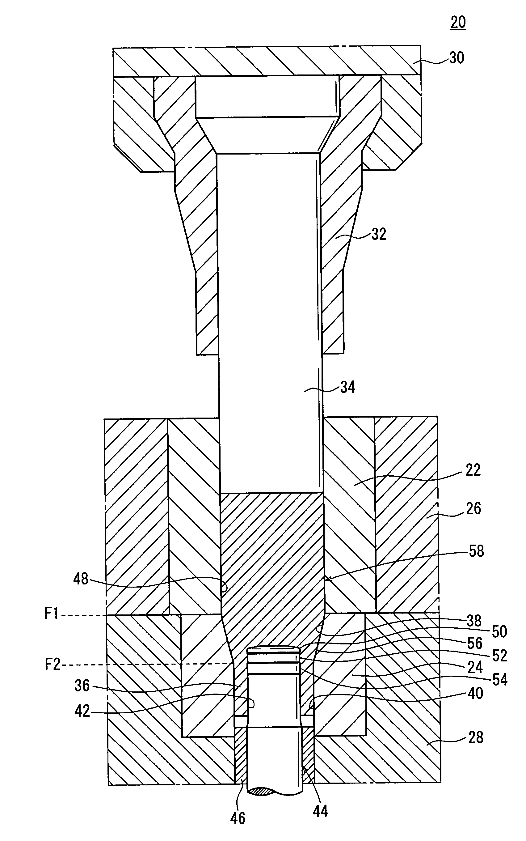
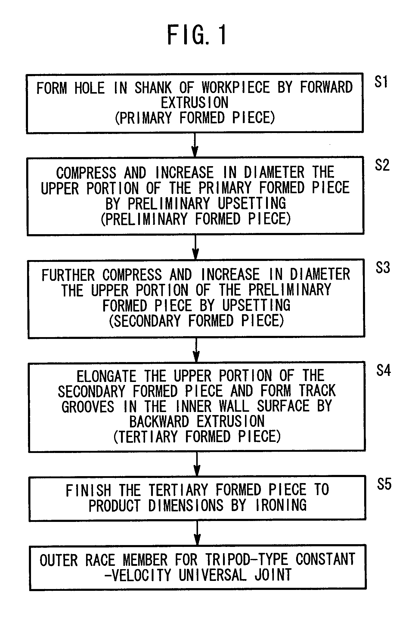
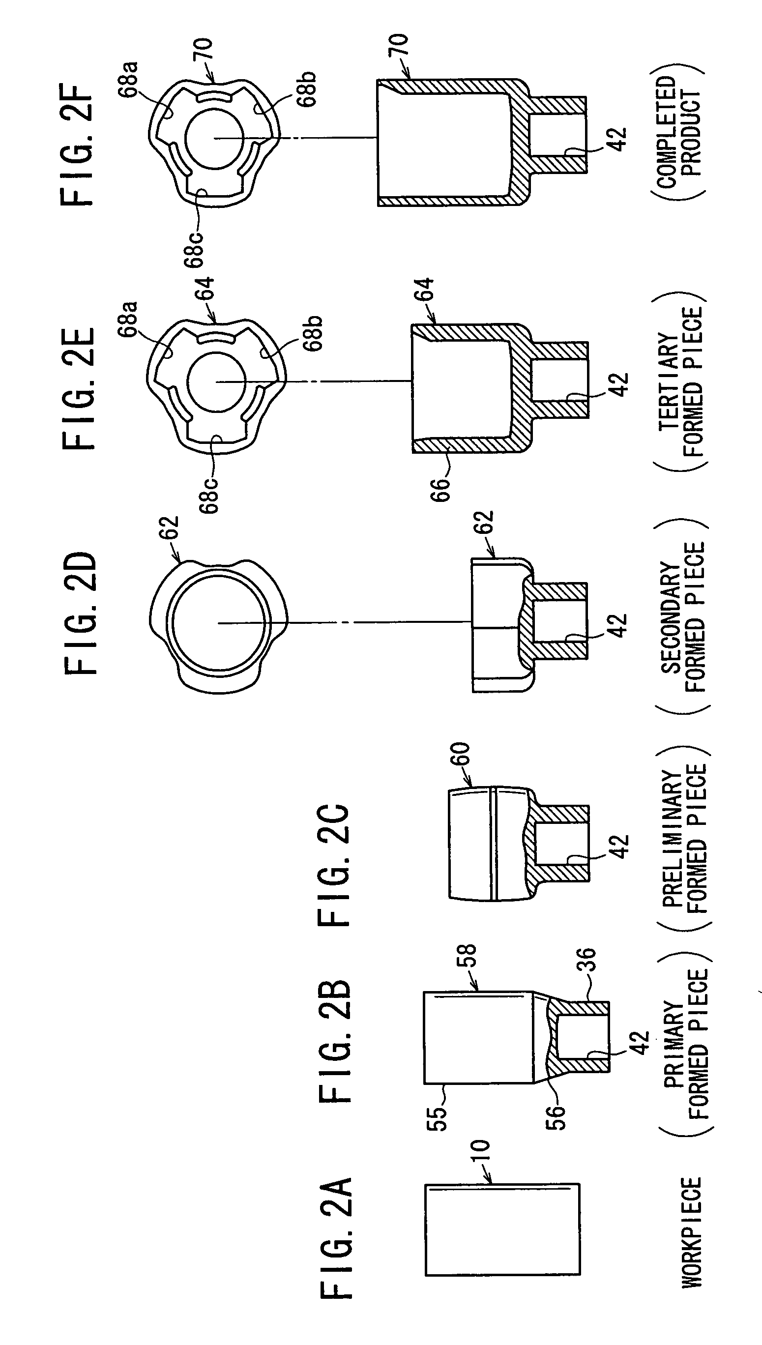
[0041]In a method for manufacturing an outer race member for a constant-velocity universal joint according to an embodiment of the present invention, as shown in the flowchart in FIG. 1, a workpiece 10 in the form of a cylinder (billet) of carbon steel is cold-forged multiple times so as to produce an outer race member for a tripod-type constant-velocity universal joint as a final product.

[0042]In a first preparatory step, the workpiece 10 (see FIG. 2A), which is cut into the form of a cylinder having a predetermined length, is treated by spheroidizing-annealing. As a result, the workpiece 10 is softened and can easily be treated in the first through fifth cold-forging steps to be described below.

[0043]In a second preparatory step, the workpiece 10 is coated with a lubricating chemical film. Specifically, a zinc phosphate lubricating chemical film is formed on the surface of the workpiece 10 by a bonderizing process in order to make the surface lubricative. Such a lubricating chemic...


PUM

PropertyMeasurementUnit
velocityaaaaaaaaaa
lengthaaaaaaaaaa
diameteraaaaaaaaaa

Abstract

An apparatus and a method for manufacturing an outer ring member for a constant velocity joint and an intermediate molded body. The apparatus includes a molding land formed in circular arc shape in cross section with a prescribed radius of curvature, a relief part continued with the molding land part, and a correcting land part continued with the relief part and larger than the outer diameter of the relief part formed at one end outer peripheral surface of a second punch for forming a hole in a shaft part drawn by a shaft part molding part. The entire part of the molding land part of the second punch is formed to be positioned between the upper end F1 and the lower end F2 of the shaft part molding part in the vertical direction of the through hole of a lower die.

Description

TECHNICAL FIELD[0001]The present invention relates to an outer race member for a constant-velocity universal joint for transmitting rotational drive power, and more particularly, to an apparatus and method for manufacturing an outer race member for a constant-velocity universal joint, which has a plurality of guide grooves formed on an inner surface of a cup, and serrations formed on an inner surface of a shank through forging, as well as an intermediate formed (molded) body of such an outer race member for a constant-velocity universal joint.BACKGROUND ART[0002]Heretofore, it has been customary to fill a cavity formed by an upper die and a lower die that are joined to each other with a forging material, and then to apply a pressing force to the forging material through a punch, for thereby producing an outer race member (outer cup) of a constant-velocity joint that is used for driving automotive wheels, for example.[0003]The outer race member comprises a tubular cup and a shank int...

Claims


Application Information

Patent Timeline
Patent Type & Authority Applications(United States)
IPC IPC(8): B21K1/04F16D3/26
CPCB21J3/00B21J5/10B21K1/762Y10T29/49689F16D3/2055F16D2250/00B21K1/765
Inventor DOI, YOSHIHISA
Owner HONDA MOTOR CO LTD
Why Eureka
Try Eureka