Putter head

a technology of putter head and shaft, which is applied in the field of putter head, can solve the problems of difficult transmission of hitting sensation to the shaft, and achieve the effect of high dimensional accuracy in the structure and easy manufacturing

Inactive Publication Date: 2009-09-15
BRIDGESTONE SPORTS
View PDF27 Cites 55 Cited by
  • Summary
  • Abstract
  • Description
  • Claims
  • Application Information

AI Technical Summary

Benefits of technology

[0005]The putter head disclosed in JP-A-2005-66249 requires high dimensional accuracy in the structure because the bar is integrally formed with the putter head. Accordingly, it is an object of the invention to provide a putter head that can be easily manufactured.
[0007]It is another object of the invention to provide a putter head that can easily transmit a feeling of hitting sensation to a shaft.
[0017]According to the aspects of the invention, the shaft fixing hole is provided in the bar, or is provided to pass through the head main body and the bar, so that a feeling of hitting sensation is easily transmitted to a shaft. In addition, the shaft is inserted into the head main body and bar and fixed thereto, and thus fixing strength of the bar increases.
[0018]According to the aspects of the invention, the recess is formed in the front end surface of the putter head, the bar insertion hole is formed in the bottom wall of the recess, and the cover, that is, the face member is mounted on the recess. Therefore, a feeling of hitting sensation is easily transmitted to the shaft.
[0019]According to the aspects of the invention, the recess is formed in the rear end surface of the putter head, the bar insertion hole is formed in the bottom wall of the recess, and the cover is mounted on the recess. Therefore, the putter head can be easily manufactured.

Problems solved by technology

Thus, it is difficult to transmit a feeling of hitting sensation to a shaft.

Method used


Image

  • Putter head
  • Putter head
  • Putter head

Examples


Embodiment Construction

[0027]An embodiment of the invention will now be described in detail with reference to FIGS. 1 to 6.

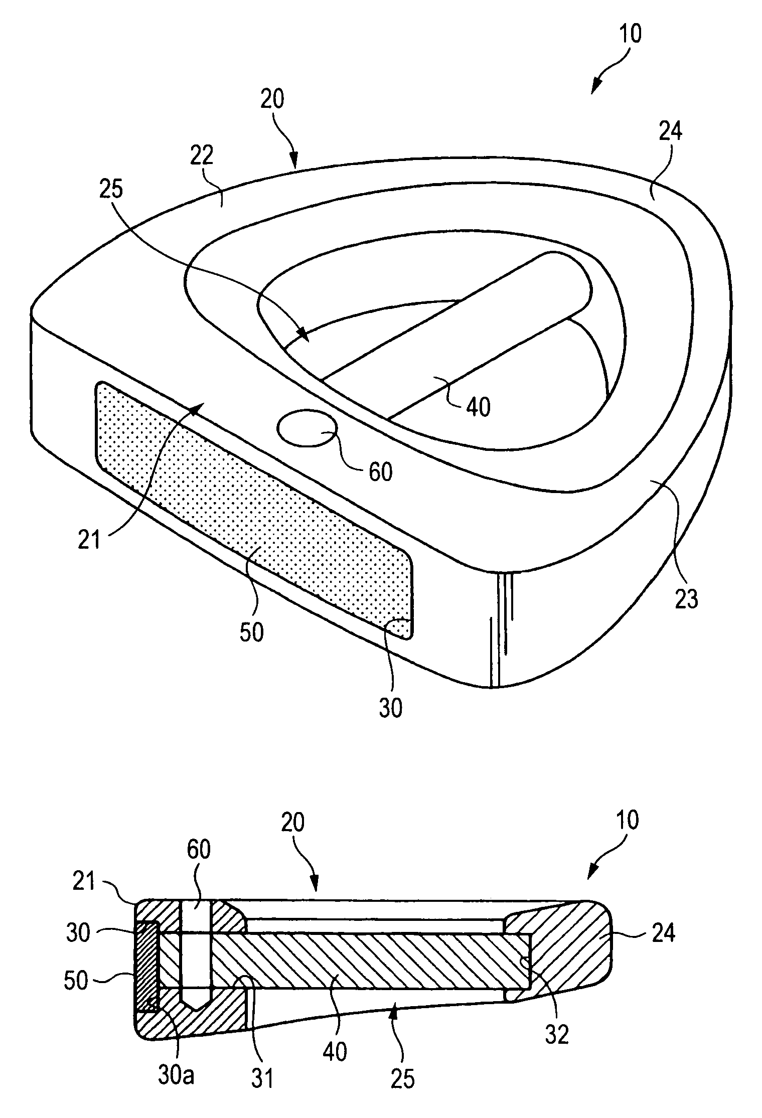
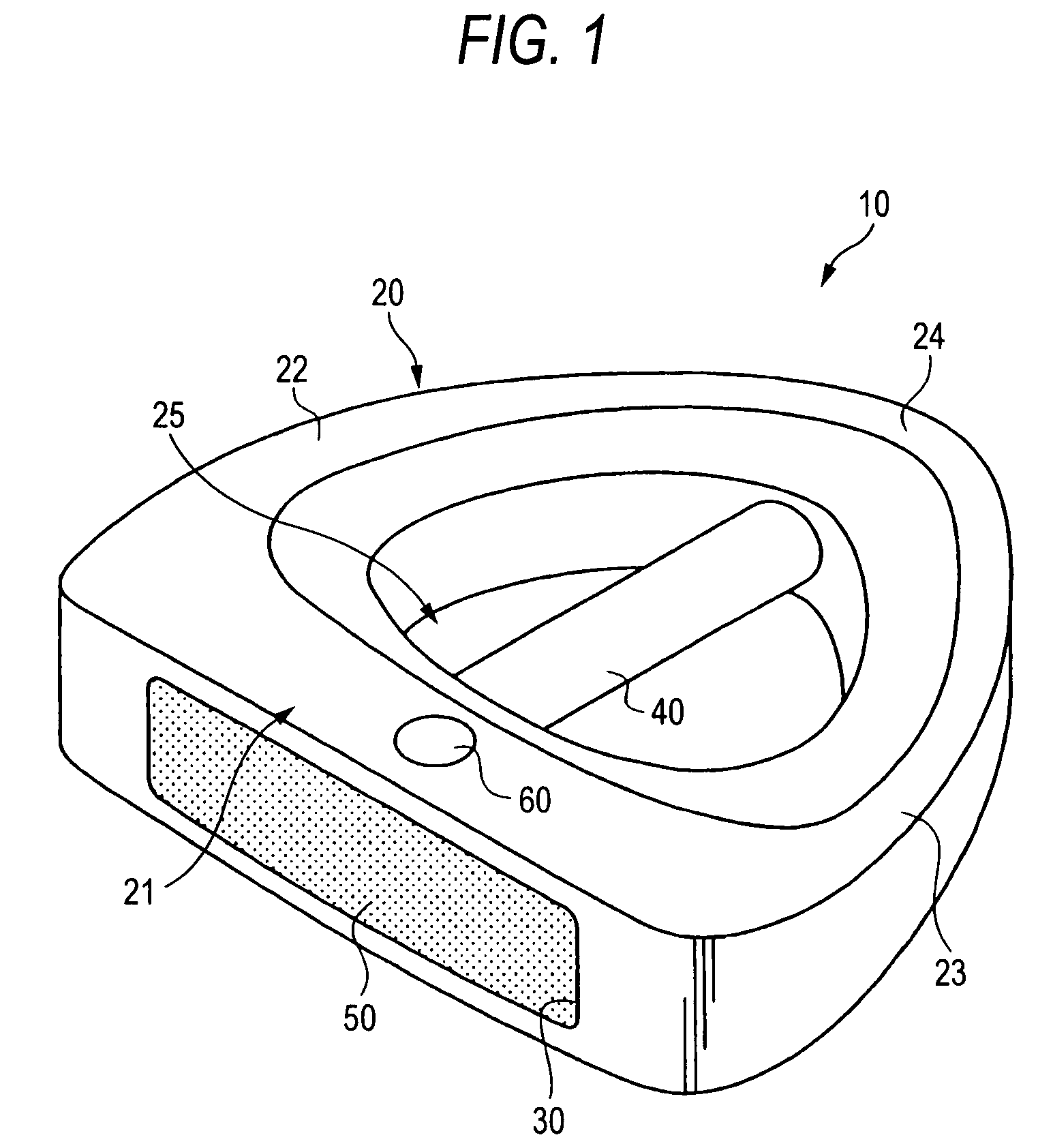
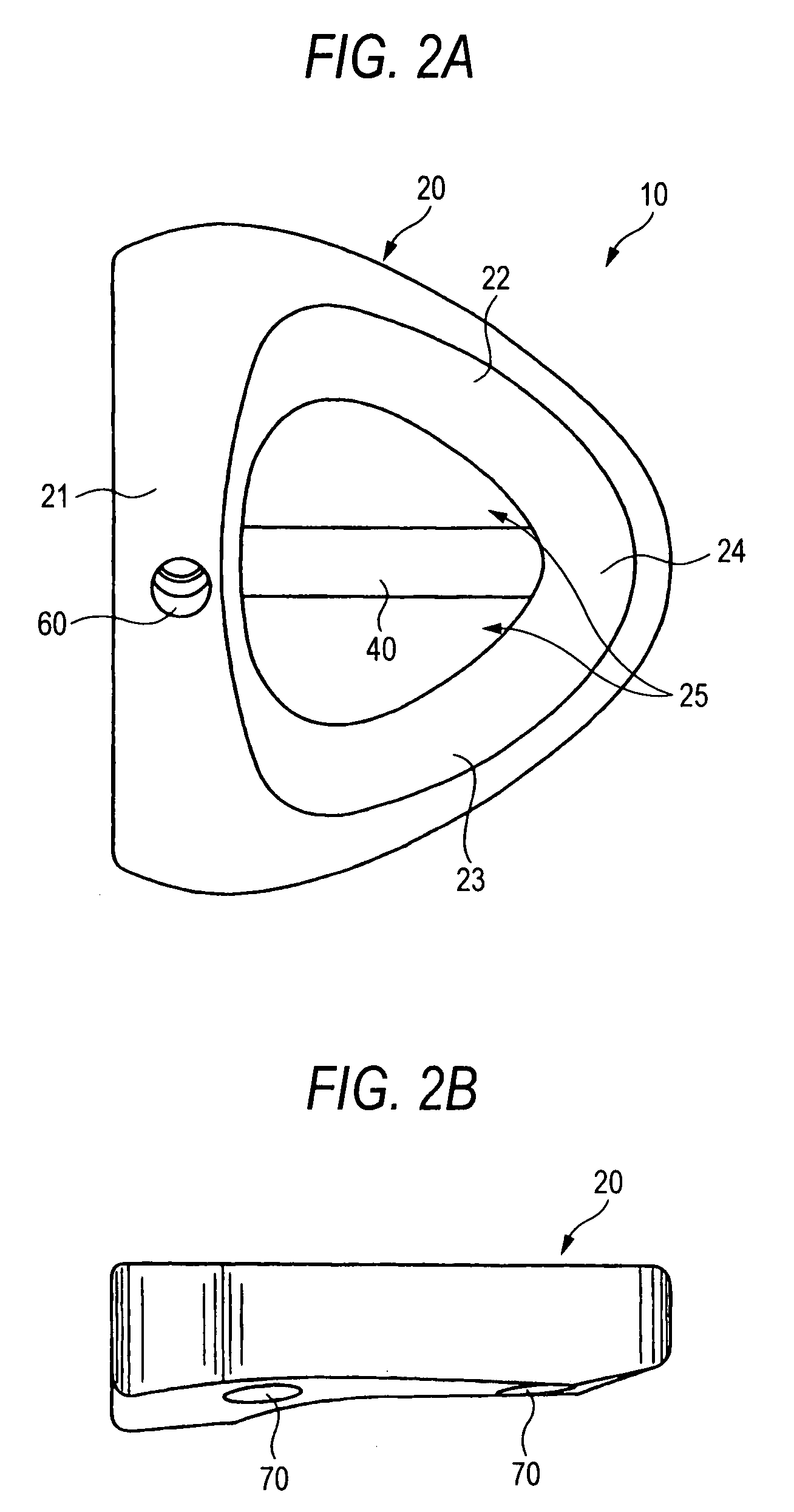
[0028]FIG. 1 is a perspective view of a putter head according to an embodiment of the invention. FIG. 2A is a plan view of the putter head. FIG. 2B is a left side view of the putter head. FIG. 3 is a front view of the putter head. FIG. 4 is a bottom view of the putter head. FIG. 5 is a rear view of the putter head. FIG. 6 is a cross-sectional view of the putter head taken along line VI-VI of FIG. 3.

[0029]A putter head 10 includes a head main body 20 that defines the outer periphery of the putter head, and a bar 40 that crosses a void space of the head main body 20 in a forward-backward direction.

[0030]The head main body 20 has a front portion 21, a tow side portion 22, a heel side portion 23, and a back portion 24 where the tow and heel side portions 22 and 23 are joined. The tow side portion 22 extends backward from the tow of the front portion 21 to the center of the back portion 24...


PUM


Abstract

A putter head includes a head main body that defines a periphery of the putter head, and a bar that crosses a void space of the head main body in a forward-backward direction. The bar is inserted into insertion holes and fixed thereto by an adhesive. A face member is mounted on a recess. A shaft fixing hole is provided to pass through the bar from the top surface of a front portion of the head main body. A shaft is inserted into the shaft fixing hole and fixed thereto by an adhesive.

Description

BACKGROUND OF THE INVENTION[0001]1. Field of the Invention[0002]The present invention relates to a putter head of a putter for golf, and in particular, to a putter head that is provided with a void space at its central part and a bar crossing the void space in a forward-backward direction.[0003]2. Description of the Related Art[0004]A putter head provided with a void space passing through the central part thereof in the thickness direction (vertical direction) and a bar crossing the void space in a forward-backward direction is disclosed in JP-A-2005-66249. By forming the void space, the moment of inertia about the gravity center is increased and the sweet area of the putter head is made larger. Further, a feeling of hitting sensation is improved by providing the bar crossing the void space in the forward-backward direction.SUMMARY OF THE INVENTION[0005]The putter head disclosed in JP-A-2005-66249 requires high dimensional accuracy in the structure because the bar is integrally form...

Claims


Application Information

Patent Timeline
Patent Type & Authority Patents(United States)
IPC IPC(8): A63B53/02A63B53/04A63B69/36A63B102/32
CPCA63B53/0487A63B59/0088A63B2053/0416A63B2053/0441A63B2053/045A63B2053/0491A63B2053/0433A63B60/02A63B60/50A63B53/0416A63B53/0433A63B53/0441A63B53/045
Inventor TATENO, ATSUO
Owner BRIDGESTONE SPORTS
Why Eureka
Try Eureka