Tool for chip removing machining as well as a solid indexable cutting insert and a solid basic body therefor

a chip removal and tooling technology, applied in the direction of cutting inserts, manufacturing tools, shaping cutters, etc., can solve the problems of extreme position precision requirements, unprogressed development, and the cutting edge in relation to the seat of the basic body may deviate to such a high degree from the desired position, so as to reduce the cost of tools

Active Publication Date: 2010-12-30
SANDVIK INTELLECTUAL PROPERTY AB
View PDF27 Cites 59 Cited by
  • Summary
  • Abstract
  • Description
  • Claims
  • Application Information

AI Technical Summary

Benefits of technology

[0006]Within the field of cutting machining, there is a continuous development with the purpose of making not only the capacity of the tools to carry out the machining in a fast and accurate way more effective, but also the manufacture of the different parts of the tools in the form of basic bodies and replaceable cutting inserts. One trend is to improve the machining results in respect of the precision and surface finish, something which requires that the active cutting edge of the cutting insert obtains an exact, predetermined spatial position in relation to the rear fixing part of the basic body. In many applications, the requirements of positional precision are extreme. In today's cutting tools, generally a positional precision of the cutting edge is therefore aimed at which is counted in thousandths of a millimeter rather than in tenths. Another trend is to reduce the costs of the manufacture of the tools. This has, among other things, led to the fact that the cutting inserts manufactured from cemented carbide, which is most common on the market, already in connection with the compression-moulding or casting and sintering have received a better and better dimensional accuracy. To obtain good precision in the cutting inserts, it was earlier always necessary to subject the same to expensive grinding operations, but by the improved moulding and sintering technique, it has become possible to use directly pressed, i.e., unground cutting inserts to an ever greater extent. However, the development has not progressed further than that the tool designer still has to allow for a dimensional variation in the order of ±0.5% of the nominal dimensions of the cutting insert. This means that the active cutting edge of the cutting insert may very well end up in the desired position in the seat, when the outcome from the cutting insert production is good, but when the outcome is poorer (so far that the cutting insert has swollen and become longer, or shrunk and become shorter than intended), the position of the cutting edge in relation to the seat of the basic body may deviate to such a high extent from the desired position that the machining precision becomes less good.

Problems solved by technology

In many applications, the requirements of positional precision are extreme.
However, the development has not progressed further than that the tool designer still has to allow for a dimensional variation in the order of ±0.5% of the nominal dimensions of the cutting insert.
This means that the active cutting edge of the cutting insert may very well end up in the desired position in the seat, when the outcome from the cutting insert production is good, but when the outcome is poorer (so far that the cutting insert has swollen and become longer, or shrunk and become shorter than intended), the position of the cutting edge in relation to the seat of the basic body may deviate to such a high extent from the desired position that the machining precision becomes less good.
When the rear clearance surfaces of the cutting insert form the reference point that determines the space position of the front, active cutting edge, the position precision of the cutting edge could become unacceptable if the cutting insert was not ground, because the distance between the active cutting edge and the opposite clearance surfaces could be considerable, in particular when the tools and the cutting inserts are large.
In certain tools, e.g., turning tools, serration connecting surfaces are, however, not suitable for different reasons, e.g., when it is desirable to make the turning inserts double-sided with the purpose of doubling the number of usable cutting edges.
Another reason is that machining of a serration connecting surface in the seat of the basic body may be difficult and expensive to carry out, in particular when the turning inserts and thereby the seats are small.
However, this merit is only theoretical so far that the location of the side contact surfaces situated far in the front or near the active cutting edge in no way guarantees an exact spatial location of the cutting edge in relation to the rear fixing part of the basic body.
Thus, there are several sources of error between the rear fixing part of the basic body and the active, front cutting edge of the cutting body.
A first source of error arises as a consequence of the fact that the seat for the cutting body is formed in a separate supplementary plate, which afterwards—via pins in co-operation with agglutination or welding—is fixed on top of a plane upperside of the basic body of the tool.
Therefore, already in the basic body, a risk arises that the exact position of the seat—and thereby of the turning insert—in relation to the rear fixing part may go lost, namely if the tolerances of the pins and the holes of the basic body co-operating with the same become poor.
In contrast to such countersunk seats that in modern cutting tools are formed by cutting or chip removing machining directly in the steel material of the basic body, the seat in the tool known by U.S. Pat. No. 4,632,606 runs in addition the risk of being dislodged from its initial position, if the turning insert during operation is subjected to great stresses.
Another source of error may be that the proper cutting body is composed of a plurality of different parts, viz. a central carrier typically of steel and two inserts of a hard material, such as cemented carbide, ceramics or diamond, applied to the same by soldering or welding.
This means that the two hard and chip-removing cutting inserts individually may obtain an erroneous (and differing) position in relation to the central carrier already in connection with the manufacture of the cutting body.
Because the carrier of the cutting body and the two separate inserts are formed of different materials, which may have different coefficients of thermal expansion, the risk of another source of error furthermore arises.

Method used


Image

  • Tool for chip removing machining as well as a solid indexable cutting insert and a solid basic body therefor
  • Tool for chip removing machining as well as a solid indexable cutting insert and a solid basic body therefor
  • Tool for chip removing machining as well as a solid indexable cutting insert and a solid basic body therefor

Examples


Embodiment Construction

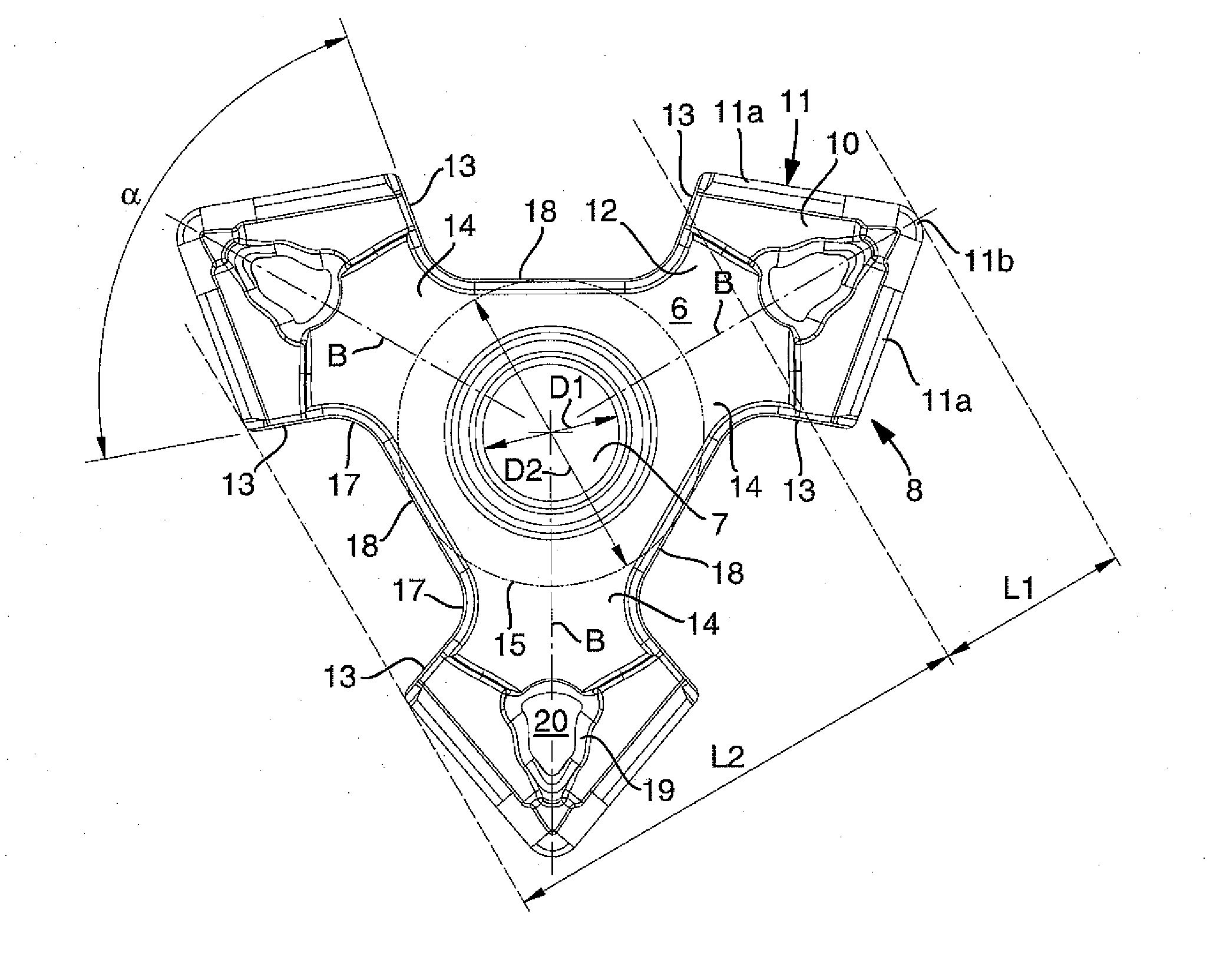
[0029]In this document, the concepts “upperside” and “underside” are used to create conceptual clarity and simplify the description of the cutting insert. These concepts are literally relevant when a cutting insert is single sided, i.e., includes cutting edges only along the periphery of the upperside. When the cutting insert (in its most preferred embodiment) is double-sided and includes cutting edges along the upperside as well as the underside, any one of the upperside and the underside can, however, be turned upward in the basic body of the tool.

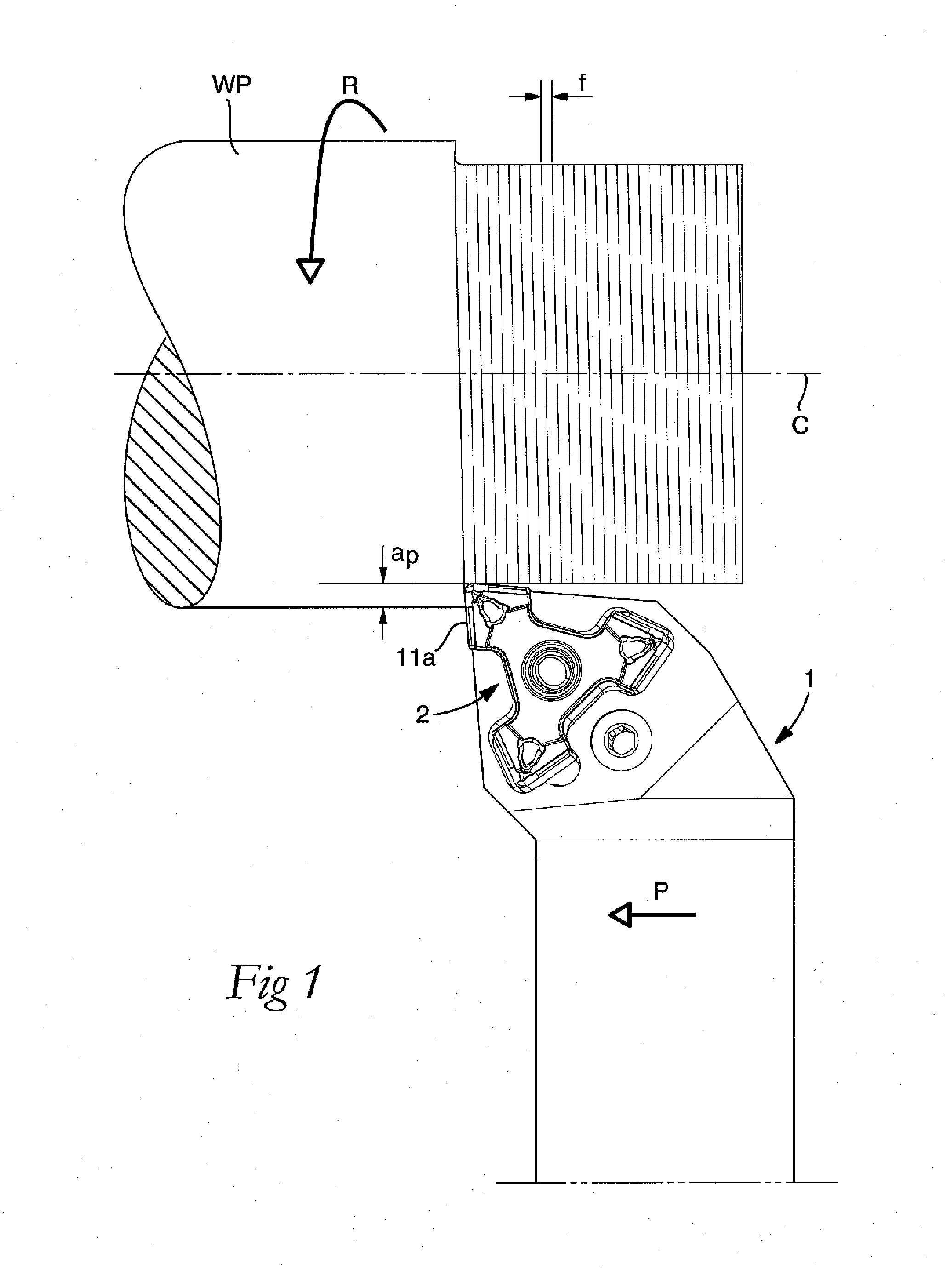
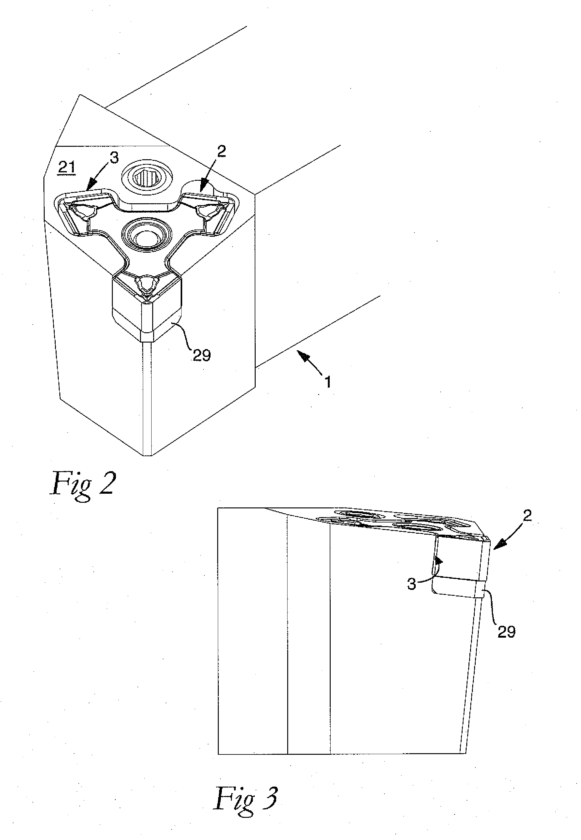
[0030]By the concept “cavity”, one of a plurality of relatively small recesses or hollows should be understood, which together with a common, central hollow space in the basic body of the tool forms a seat in which the cutting insert can be placed. Each such cavity has the purpose of housing a head formed in the cutting insert irrespective of whether a cutting edge included in the same is active or not.

[0031]Although the invention could ...


PUM

PropertyMeasurementUnit
angleaaaaaaaaaa
angle of convergenceaaaaaaaaaa

Abstract

A tool for chip removing machining, including a basic body having an insert seat, and an indexable cutting insert fixed in the seat. The insert includes an upperside, an underside, a pair of side contact surfaces, two cutting edges that individually extend along a chip surface included in one of the upperside and underside, at least two heads that are spaced-apart via an intermediate part and individually include a front portion having at least one cutting edge and a rear portion along which the pair of side contact surfaces are formed. The insert seat of the basic body includes a central hollow space, and a front cavity and at least one rear cavity in which the heads of the cutting insert are housed, the front cavity including a pair of side support surfaces against which the pair of side contact surfaces of the cutting insert are pressed when a tightening element pulls the head rearward toward the side support surfaces. The basic body is solid by being formed integrally of steel material. The seat is countersunk in the basic body such that the side support surfaces are integrated in the steel material. The cutting insert is formed integrally from a second, hard-wearing material having at least the same hardness as cemented carbide, the pair of side contact surfaces of the insert being integrated in the second material.

Description

[0001]This application claims priority under 35 U.S.C. §119 to Swedish Patent Application No. 0900865-7, filed on Jun. 24, 2009, which is incorporated by reference herein in its entirety.FIELD OF THE INVENTION[0002]The present invention relates generally to a tool for chip removing machining, including a basic body having an insert seat, and an indexable cutting insert fixed in the seat. The insert includes an upperside, an underside, a pair of side contact surfaces, two cutting edges that individually extend along a chip surface included in one of the upperside and underside, at least two heads that are spaced-apart via an intermediate part and individually include a front portion having at least one cutting edge and a rear portion along which the pair of side contact surfaces are formed. The insert seat of the basic body includes a central hollow space, and a front cavity and at least one rear cavity in which the heads of the cutting insert are housed, the front cavity including a...

Claims


Application Information

Patent Timeline
Patent Type & Authority Applications(United States)
IPC IPC(8): B26D7/18
CPCB23B27/145B23B27/1622B23B2200/048B23B2200/204Y10T407/2274B23B2205/16Y10T407/235Y10T407/23B23B2205/12B23C5/22B23B27/16
Inventor EDLER, DANIELENGLUND, KJELL
Owner SANDVIK INTELLECTUAL PROPERTY AB
Why Eureka
Try Eureka