Cooling plate for a metallurgical furnace

Active Publication Date: 2012-03-08
PAUL WURTH SA
View PDF2 Cites 8 Cited by
  • Summary
  • Abstract
  • Description
  • Claims
  • Application Information

AI Technical Summary

Benefits of technology

[0007]The invention provides an alternative cooling plate that i

Problems solved by technology

In the furnace, the cooling plates with their concrete/refractory lining are subject to important heat and mechanical deformation resulting from high fluxes in the blast furnaces.
The concrete/r

Method used


Image

  • Cooling plate for a metallurgical furnace
  • Cooling plate for a metallurgical furnace
  • Cooling plate for a metallurgical furnace

Examples


Embodiment Construction

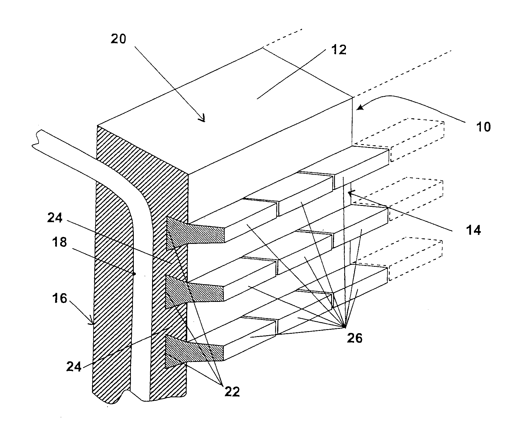
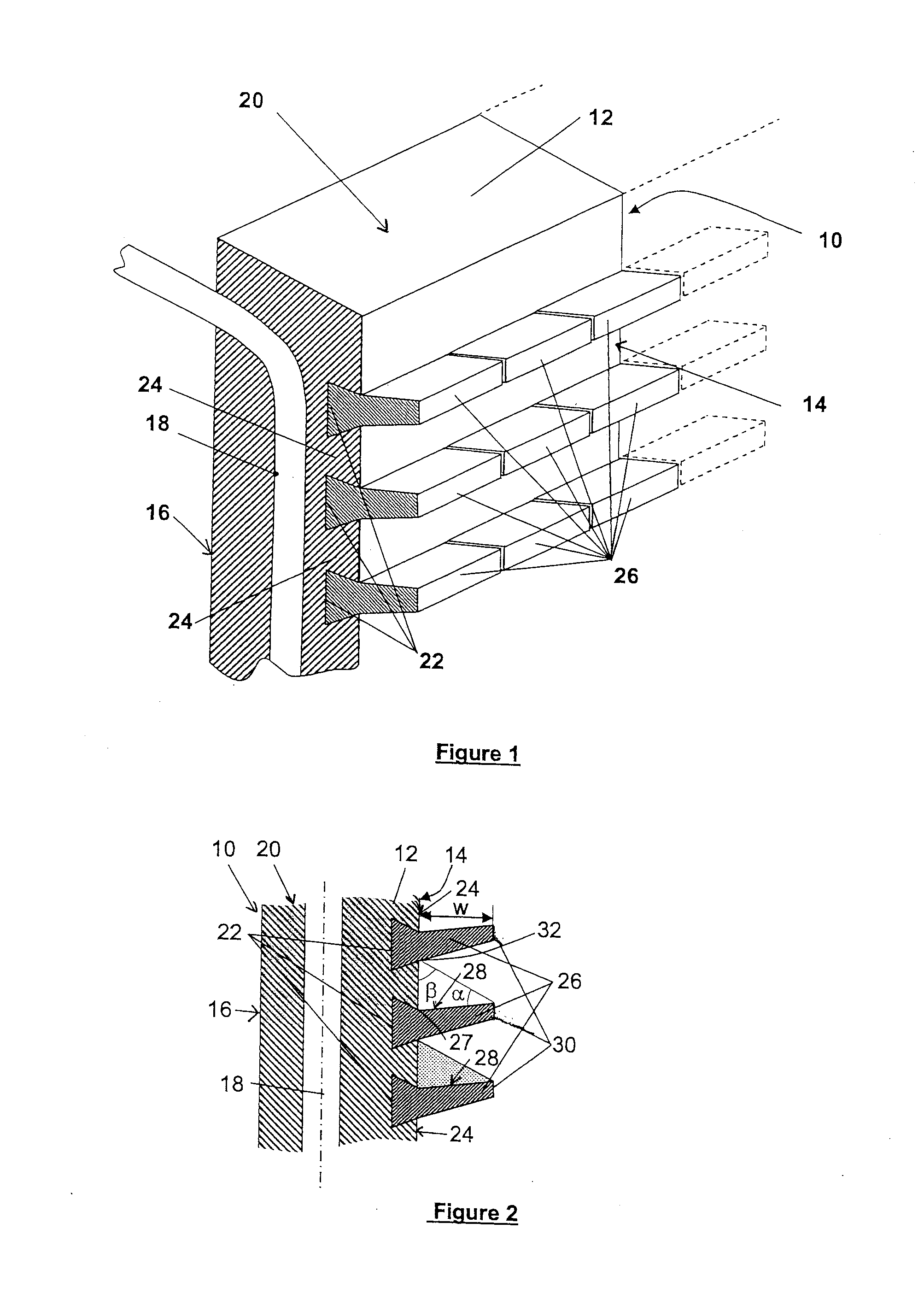
[0029]A preferred embodiment of the present cooling plate 10 is illustrated in FIGS. 1 and 2. The cooling plate 10 is typically formed from a slab e.g. made of a cast or forged body of copper, copper alloy or steel into a panel-like body 12. This panel-like metallic body 12 has a front face 14, also referred to as hot face, which will be facing the interior of the furnace, and a rear face 16, also referred to as cold face, which will be facing the inner surface of the furnace wall. Conventionally, the panel-like body 12 is of essentially parallelepipedic form. Most modern cooling plates have a width in the range of 600 to 1300 mm and a height in the range of 1000 to 4200 mm. It will however be understood that the height and width of the cooling plate may be adapted, amongst others, to structural conditions of a metallurgical furnace and to constraints resulting from their fabrication process.

[0030]A plurality of coolant channels 18 extend through the body 12 in proximity of the rear...


PUM

PropertyMeasurementUnit
Angleaaaaaaaaaa
Angleaaaaaaaaaa
Angleaaaaaaaaaa

Abstract

A cooling plate (10) for a metallurgical furnace comprises a body (12) with a front face (14) and an opposite rear face (16), as well as coolants channel (18) therein; a plurality of lamellar ribs (24) on its front face, two consecutive ribs (24) being spaced by a groove (22); and inserts (26) fixed in the grooves (22) and projecting from the front face (14). The inserts (26) have an upper side projecting from the bottom edge of the rib directly above, which is configured so as to form a collecting surface (28) on which, in use, furnace burden material accumulates up to the top edge (32) of the rib (24) directly above.

Description

TECHNICAL FIELD[0001]The present invention generally relates to a cooling plate for a metallurgical furnace and its method of manufacturing.BACKGROUND ART[0002]Cooling plates for metallurgical furnaces, also called staves, are well known in the art. They are used to cover the inner wall of the outer shell of the metallurgical furnace, as e.g. a blast furnace or electric arc furnace, for two main reasons. The first function of the cooling plates is to provide a heat evacuating protection screen between the interior of the furnace and the outer furnace shell.[0003]Originally, the cooling plates have been cast iron plates with cooling pipes cast therein. As an alternative to cast iron staves, copper staves have been developed. Nowadays, most cooling plates for metallurgical furnaces are made of copper, copper alloy or, more recently, of steel.[0004]The second function of the cooling plates is to provide an anchoring means for a refractory brick lining, a refractory guniting or a proces...

Claims


Application Information

Patent Timeline
IPC IPC(8): F27D9/00B21D53/02
CPCC21B7/10F27B1/24Y10T29/4935F27D2009/0051F27D1/12F27B3/24
Inventor MAGGIOLI, NICOLASGARRATT, DALLAS
Owner PAUL WURTH SA
Why Eureka
Try Eureka