Carrying container folded from a die cut sheet material

a die-cut sheet material and carrier container technology, applied in the field of carriers, can solve the problems of object falling from the receiving cavity, relative weak loading structure, and weak strength of the base panel, and achieve the effect of enhancing structural strength and integrity

Inactive Publication Date: 2014-03-18
LIU AN HSIA +3
View PDF32 Cites 0 Cited by
  • Summary
  • Abstract
  • Description
  • Claims
  • Application Information

AI Technical Summary

Benefits of technology

[0010]A main object of the present invention is to provide a carrying container which is conveniently folded from die cut sheet materials for forming a carrying container comprising a packaging reinforcing arrangement, wherein the packaging reinforcing arrangement which is capable of substantially enhancing a structural strength and integrity of the carrying container.
[0011]Another object of the present invention is to provide a carrying container comprising a container body for supporting the objects stored within the carrying container, wherein the container body comprises a bottom wall which forms a one-piece panel structure for maximizing the structural strength of the container body.
[0012]Another object of the present invention is to provide a carrying container having double sidewall structure for resisting external impact from two sides of the carrying container.

Problems solved by technology

Therefore, the folding structure of the conventional carrying container has a relatively weak loading structure to support the object.
There are several disadvantages in association with this kind of carrying container.
The problem with this kind of conventional arts is that the base panel is usually formed by folding a plurality of flaps so that the base panel is actually made up by the flaps interlocking with each other for supporting the object within the receiving cavity.
Very often, therefore, the structural strength of the base panel is usually not strong enough to such an extent that when the carrying container is subject to external impact, or when the object carried within the carrying container is fairly heavy, the base panel may break and cause the object to fall from the receiving cavity.
Second, even when the base panel does not suffer from structural instability, the entire structure of the carrying container may be so vulnerable to external impact that the container may collapse rather easily.
In such scenario, the objects stored within the receiving cavity cannot be properly protected and this disadvantage may cause undue damage to the objects carried by the conventional carrying container.
Third, some of the conventional carrying containers require some sorts of adhesive equipments, such as tapes, for enhancing the structural strength of the carrying containers.
This is troublesome from the point of view of the users, as well as from the point of view of those who wish to disassemble the carrying containers for consuming the objects within the receiving cavity.
Fourth, many conventional carrying containers do not have handles.
The problem with this design is that in the vicinity of the handling slots, the carrying container has less structural strength than any other part thereof so that the relevant area (i.e. area in the vicinity of the handling slots) may break very easily, especially when the carrying container is carrying heavy objects.

Method used


Image

  • Carrying container folded from a die cut sheet material
  • Carrying container folded from a die cut sheet material
  • Carrying container folded from a die cut sheet material

Examples


Embodiment Construction

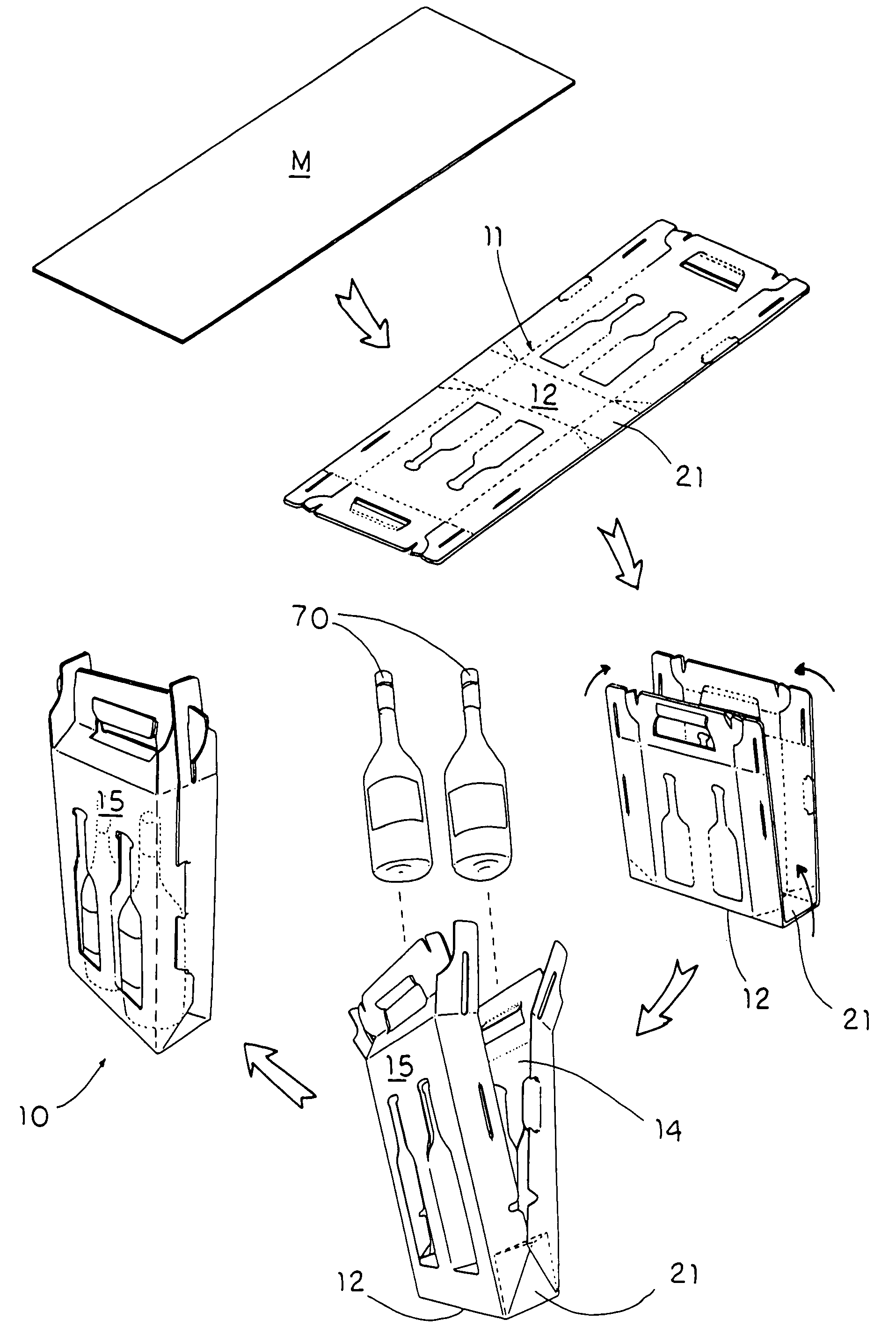
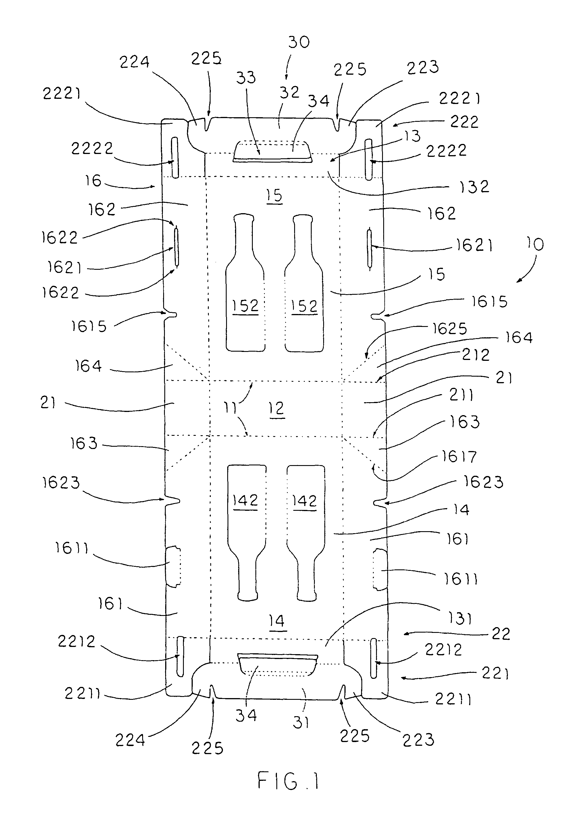
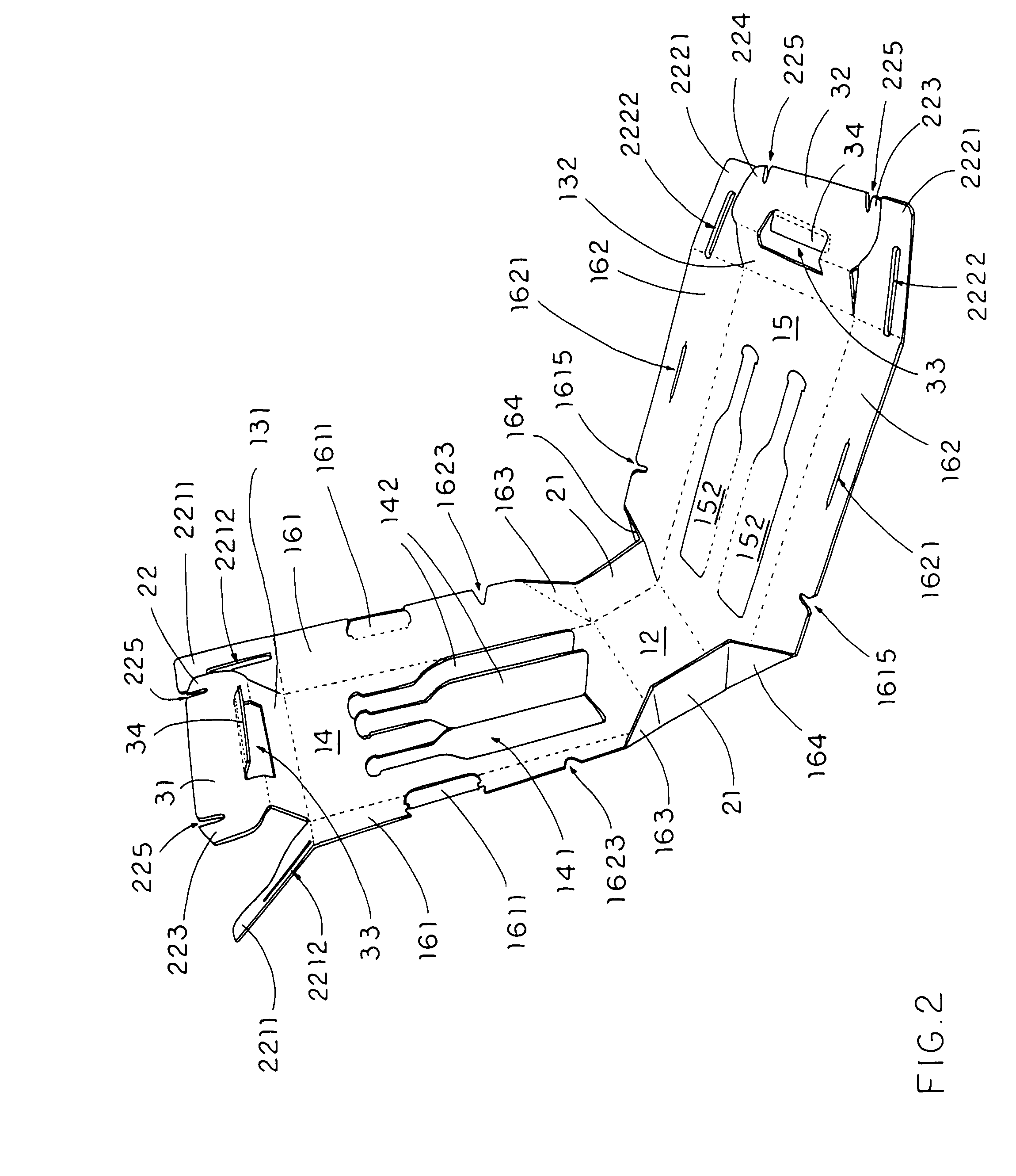
[0030]Referring to FIG. 1 to FIG. 3 of the drawings, a carrying container for at least an object, such as two wine bottles 70, according to a preferred embodiment of the present invention is illustrated, in which the carrying container comprises a container body 10, and a packaging reinforcing arrangement 20.

[0031]The container body 10, which is made of a one-piece panel structure having a plurality of folding lines 11 provided thereon, comprises a bottom wall 12, a top wall 13, a front wall 14 integrally extended from a front peripheral edge of the top wall 13 to a front peripheral edge of the bottom wall 12, a rear wall 15, which is similar to the front wall 14, integrally extended from a rear peripheral edge of the top wall 13 to a rear peripheral edge of the bottom wall 12, and two side walls 16 extended from two sides peripheral edges of the front wall 14 to two side peripheral edges of the bottom walls 12 respectively to form a substantially cubic structure of the container an...


PUM

PropertyMeasurementUnit
weightaaaaaaaaaa
weightaaaaaaaaaa
structural strengthaaaaaaaaaa

Abstract

A carrying container for bottles includes a container body and a packaging reinforcing arrangement. The container body, which is made of a one-piece panel structure having a plurality of folding lines provided thereon, includes a bottom wall, a top wall, a front wall, a rear wall, and two side walls to form a substantially cubic structure of the container and to define a receiving cavity. The packaging reinforcing arrangement includes two reinforcing walls integrally extended from two side edges of the bottom wall to the two side walls respectively, and supported within the receiving cavity at a position that a front reinforcing edge and a rear reinforcing edge of each of the reinforcing walls are biasing against inner surfaces of the front and rear walls of the container body for effectively resisting an external impact force.

Description

CROSS REFERENCE OF RELATED APPLICATION[0001]This is a non-provisional application for a provisional application having an application number of 60 / 831,164 and a filing date of Jul. 15, 2006.BACKGROUND OF THE PRESENT INVENTION[0002]1. Field of Invention[0003]The present invention relates to a container, and more particularly to a carrying container comprising a packaging reinforcing arrangement which is capable of substantially enhancing a structural strength and integrity of the carrying container.[0004]2. Description of Related Arts[0005]A conventional carrying container, such as a conventional CARTON, usually comprises a container body having a front panel, a rear panel, a top panel, a base panel, and two side panels for forming a receiving cavity within these panels for receiving a predetermined object, such as a wine bottle. All these panels are usually made of die cut sheet materials which make the carrying container easy to assemble, and light to carry. However, when the carry...

Claims


Application Information

Patent Timeline
Patent Type & Authority Patents(United States)
IPC IPC(8): B65D75/00
CPCB65D5/4802B65D5/46112B65D5/18
Inventor LIU, AN-HSIALIU, VICTOR D.LIU, ALEXANDER D.LIU, WEN-SHUEH M.
Owner LIU AN HSIA
Why Eureka
Try Eureka