Soft tissue tunneling device

a soft tissue and tunneling technology, applied in the field of soft tissue tunneling devices, can solve the problems of patient discomfort, sharp tips that may damage tissue and/or nerves,

Active Publication Date: 2014-03-18
AVENT INC
View PDF30 Cites 0 Cited by
  • Summary
  • Abstract
  • Description
  • Claims
  • Application Information

AI Technical Summary

Benefits of technology

[0006]A need exists for an improved tunneling device with a blunt distal tip to minimize coring of tissue and other damage associated with advancing an object within the body. The tunneling device may optionally include a retractable needle to assist in puncturing the skin prior to advancing the tunneling device within the patient's body. In addition, a tunneling device with a shapeable malleable shaft will assist in the accurate delivery of the device into the anatomy. Moreover, a tunneling device configured to deliver fluid, anesthetic or other medication to the tissue adjacent the tunneling device will alleviate the discomfort associated with such procedures.
[0008]A preferred embodiment involves a tunneling device for creating a subcutaneous path for placement of a catheter in a patient. The tunneling device includes an elongate shaft having a rounded distal end. A handle is secured to the shaft. The handle is configured to permit a user of the tunneling device to manually manipulate the tunneling device. A sheath (e.g., sheath, IV catheter, angio-catheter, other exterior member, etc.) is positionable over a portion of the shaft. The sheath has a snug fit with the shaft such that the sheath and the shaft can be advanced together within a body of a patient.
[0013]One embodiment includes a tunneling device for creating a path for placement of a catheter or other item within an anatomy of a patient. The tunneling device includes an elongated shaft having a generally rounded distal end, a handle secured to said shaft and having a distal end, and a sheath slidably positioned over a portion of said shaft. The handle is configured to permit a user to grasp and manipulate said tunneling device. In some embodiments, the sheath has a generally snug fit with said shaft such that said sheath and said shaft can be advanced together within the anatomy. In other embodiments, the sheath has a generally loose fit relative to said shaft. The distal end of said handle includes a groove that is configured to receive at least a portion of a proximal end of the sheath so as to substantially prevent relative rotation and / or other movement between the shaft and the sheath when the tunneling device is being manipulated within an anatomy.
[0017]According to some embodiments, a method of introducing a tunneling device into a body includes grasping a handle of a tunneling device. The tunneling device includes an elongated shaft having a rounded distal end and defining at least one interior lumen. In addition, the tunneling device includes one or more fluid exit openings that are configured to be in fluid communication with said interior lumen. The method additionally includes positioning a sheath over at least a portion of the elongated shaft of the tunneling device, securing the sheath to the handle of the tunneling device so as to prevent relative rotation between the sheath and the shaft during use of the tunneling device, introducing said tunneling device into the body of a patient, advancing said tunneling device within the body and administering a fluid through said interior lumen and into the body of the patient.

Problems solved by technology

However, catheters often require stiff, hollow introducer needles for placement within the anatomy.
Typically, such introducer needles have sharp tips that may damage tissue and / or nerves during their delivery into a body.
This trauma may also result cause discomfort for the patient.

Method used


Image

  • Soft tissue tunneling device
  • Soft tissue tunneling device
  • Soft tissue tunneling device

Examples


Embodiment Construction

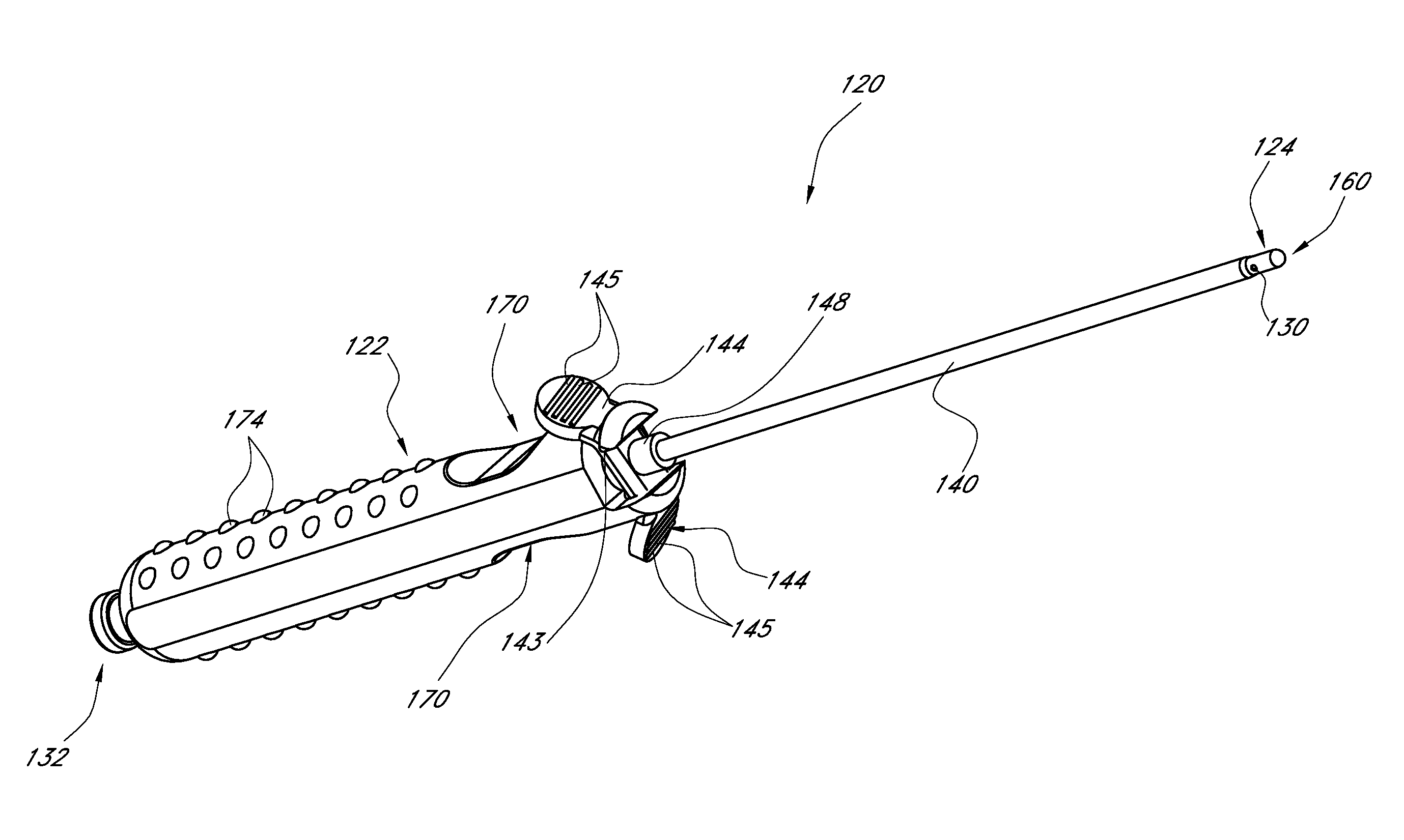
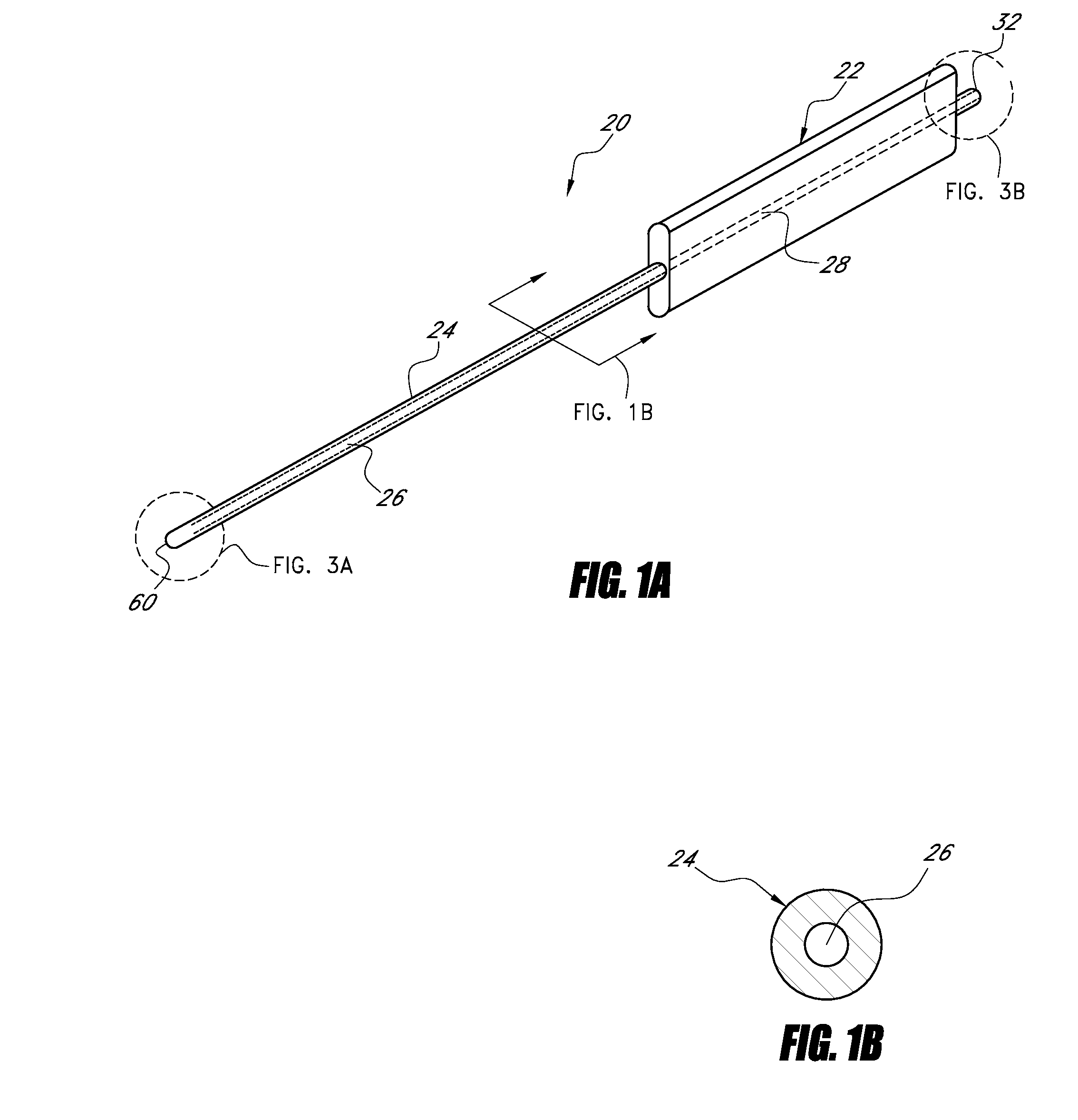
[0042]FIG. 1A illustrates a soft tissue tunneling device 20 according to one embodiment of the present invention. The tunneling device 20 preferably includes a handle 22, a shaft 24 and at least one lumen 26 located within the shaft 24. The handle 22 can be constructed of one or more types of plastic or other synthetic or semi-synthetic polymerization product. Alternatively, the handle 22 may be constructed of metal and / or any other suitable material or combination of materials. As illustrated in FIG. 1A, the handle 22 has a generally rectangular shape in cross-section with rounded edges. Preferably, the handle 22 is easy to grip to assist the user in grasping and manipulating the tunneling device 20. The handle 22 can be manufactured with smooth corners and / or other surfaces to reduce any discomfort of handling the tunneling device 20. Further, the handle may have a plurality of molded finger grooves or the like for enhanced gripability. Moreover, a portion or the entire handle 22 ...


PUM


Abstract

A tissue tunneling device is configured to be delivered within the body. The tunneling device includes a shaft with a blunt distal end to prevent coring or other damage to tissue during the delivery of the tunneling device. In some arrangements, the shaft includes one or more lumen, through which medication or another fluid may be administered. An anesthetic or other pain relieving medication may be delivered through the lumen to lessen the discomfort of delivering the tunneling device to the desired anatomical site. The handle of the tunneling device can be adapted to receive a syringe or another type of fluid source. The shaft may also include a retractable needle for facilitating the advancement of the tunneling device through skin or other tissue. The shaft may also be provided with an outer sheath, which may be left within the anatomy after the tunneling device has been removed. The tunneling device can be configured to prevent or reduce relative rotation or other movement between the shaft and the sheath. The shaft may be malleable for custom-shaping the tunneling device prior to and / or during delivery.

Description

RELATED APPLICATIONS[0001]This application is a continuation-in-part of U.S. patent application Ser. No. 11 / 744,667, filed May 4, 2007, pending, which claims the priority benefit under 35 U.S.C. §119(e) of U.S. Provisional Application No. 60 / 798,238, filed May 5, 2006, both of which are hereby incorporated by reference in their entireties.BACKGROUND OF THE INVENTIONS[0002]1. Field of the Inventions[0003]This invention generally relates to soft tissue tunneling devices and, in particular, to an improved tunneling device for the introduction of a catheter into the body of a patient.[0004]2. Description of the Related Art[0005]Devices used to administer a fluid inside the anatomy are well known. Hypodermic needles, catheters and the like are often used to deliver medication and other fluids to targeted sites within the body. In many instances, catheters are preferred because they can deliver fluid to a particular site over a period of time. However, catheters often require stiff, hollo...

Claims


Application Information

Patent Timeline
Patent Type & Authority Patents(United States)
IPC IPC(8): A61M5/178
CPCA61B17/3415A61M25/0194
Inventor MASSENGALE, ROGERKHALAJ, STEVE
Owner AVENT INC
Why Eureka
Try Eureka