Antennas

a technology of reflectors and antennas, applied in non-linear optics, instruments, thermoelectric devices, etc., can solve the problems of complex optical design and components required

Active Publication Date: 2014-03-25
MBDA UK
View PDF35 Cites 174 Cited by
  • Summary
  • Abstract
  • Description
  • Claims
  • Application Information

AI Technical Summary

Benefits of technology

[0010]The second frequency band may include two or more sub-b

Problems solved by technology

One problem introduced when a Cassegrain antenna is used within such a dual mode seeker is that complicated optical design and components a

Method used


Image

  • Antennas
  • Antennas
  • Antennas

Examples


Embodiment Construction

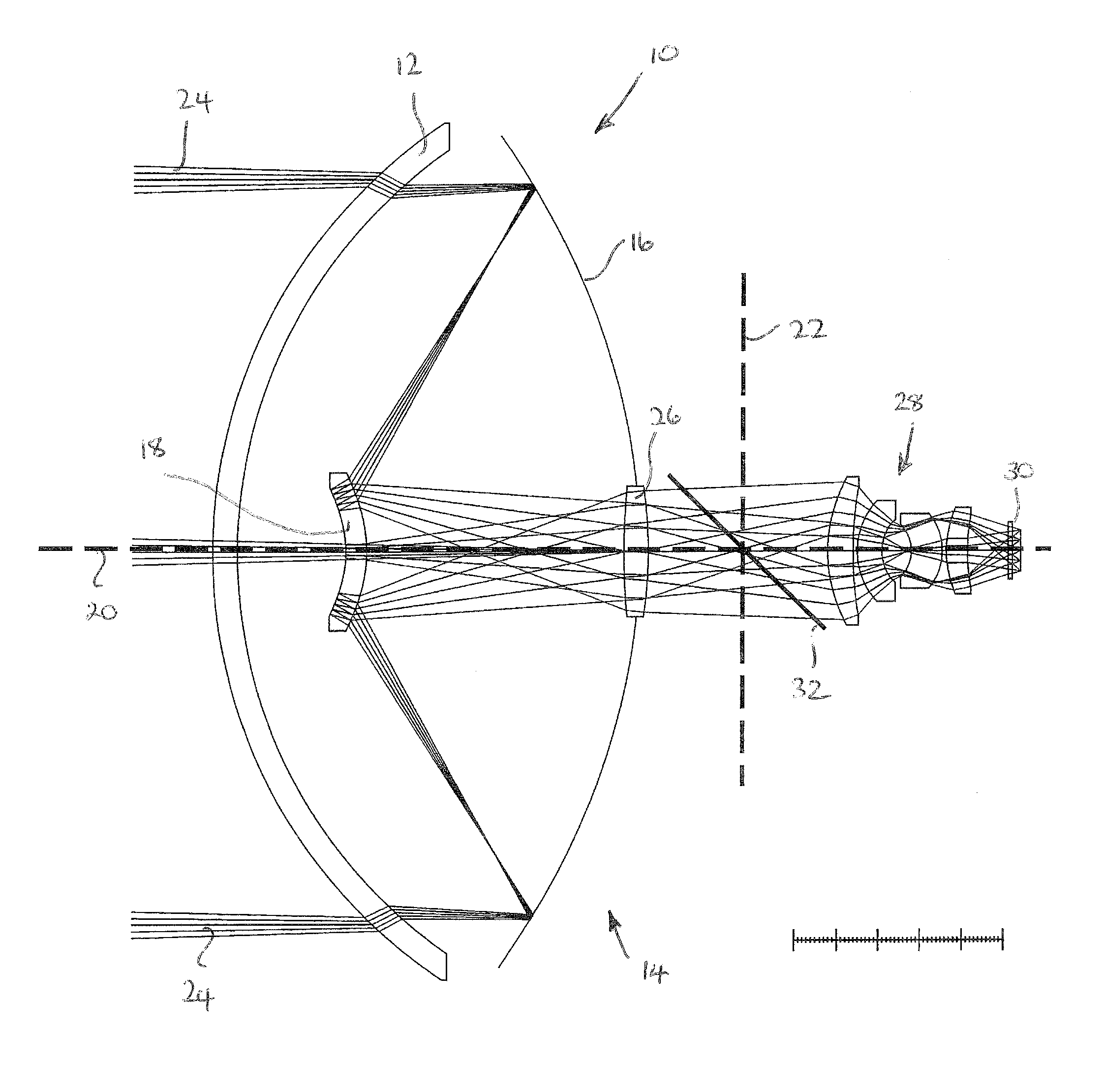
[0023]Millimeter wave radar seekers provide a strong capability in the engagement of surface based targets. Performance can be enhanced by augmenting such radar seekers with a complementary infra-red sensor, especially when the radar seeker is to be used in short range, terminal operations where near visual target confirmation is required prior to engagement with the target.

[0024]As there is a limited space within a missile, it is necessary to incorporate a Cassegrain antenna system within the missile head to provide the necessary focal length to correctly receive both radar and infra-red frequencies within the size constraints of the missile. Furthermore, to house components associated with transmission and / or reception of both infra-red and radio frequency bands within the missile, it is necessary for the radar seeker to be designed in such a manner that infra-red and radio frequency channels share the primary and secondary reflector elements of the Cassegrain antenna system in a ...


PUM


Abstract

A reflector 38 includes a mirrored surface 48 and a frequency selective surface 46. The frequency selective surface 46 is arranged to reflect radiation of a first frequency band 52 and allow radiation of a second frequency band 50 to pass. The mirrored surface 48 is arranged to reflect radiation of the second frequency band 50. In this manner, the focal power for radiation of the first frequency band 52 is independent to the focal power for radiation of the second frequency band 50. Accordingly, the design of optical components associated with the second frequency band 50 can be undertaken independently of those associated with the first frequency band 52 so as to achieve the optimised focusing for each frequency band.

Description

BACKGROUND OF THE INVENTION [0001]The present invention relates to a reflector and an antenna system, in particular to a reflector and an antenna system arranged to transmit and / or receive radiation of two frequency bands. Such a reflector or antenna system may be used within a seeker system of a missile.[0002]According to EP1362385, a missile seeker arrangement can include a Cassegrain antenna system mounted within the radome of the missile. Such a Cassegrain antenna incorporates a parabolic shaped primary reflector and a hyperbolic shaped secondary reflector.[0003]The secondary reflector is mounted to the primary reflector via a support. The support is made from a dielectric material having a thickness selected to minimise transmission loss.[0004]The primary reflector is mounted on a gimbal arrangement so as to be articulated about either roll or pitch axes with respect to the missile. In this manner a greater field of view can be provided for the seeker arrangement.[0005]The seco...

Claims


Application Information

Patent Timeline
IPC IPC(8): H01Q19/19F41G7/20F41G7/00H01Q19/00
CPCH01Q1/28H01Q19/195F41G7/2293F41G7/2253H01Q19/062H01Q19/19F41G7/2286H01Q15/0013F41G7/2246H01Q15/14F41G7/008
Inventor PRITCHARD, TIMOTHY, JOHN
Owner MBDA UK
Why Eureka
Try Eureka