Dynamic frequency selective surfaces

a frequency selective surface and dynamic technology, applied in the field of frequency selective surfaces, can solve problems such as the loss of acceptable signal reception of the ssa system

Active Publication Date: 2005-08-18
APTIV TECH LTD
View PDF26 Cites 48 Cited by
  • Summary
  • Abstract
  • Description
  • Claims
  • Application Information

AI Technical Summary

Problems solved by technology

During this time, the SSA system loses acceptable signal reception.

Method used


Image

  • Dynamic frequency selective surfaces
  • Dynamic frequency selective surfaces
  • Dynamic frequency selective surfaces

Examples


Embodiment Construction

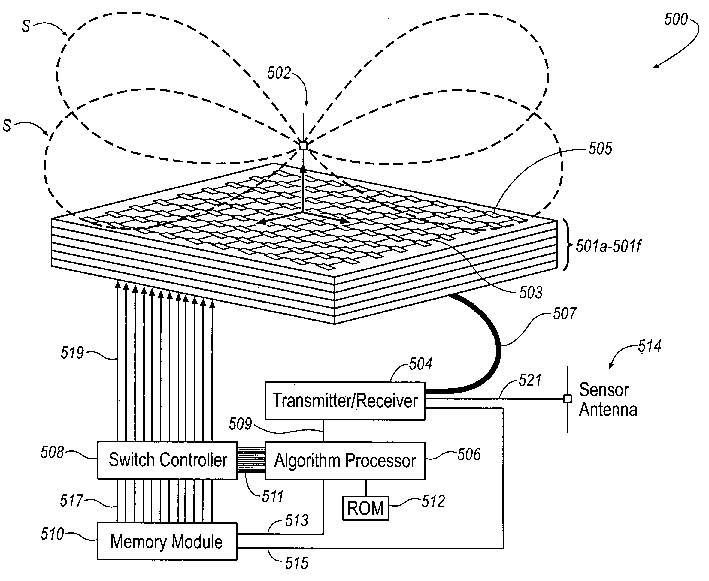
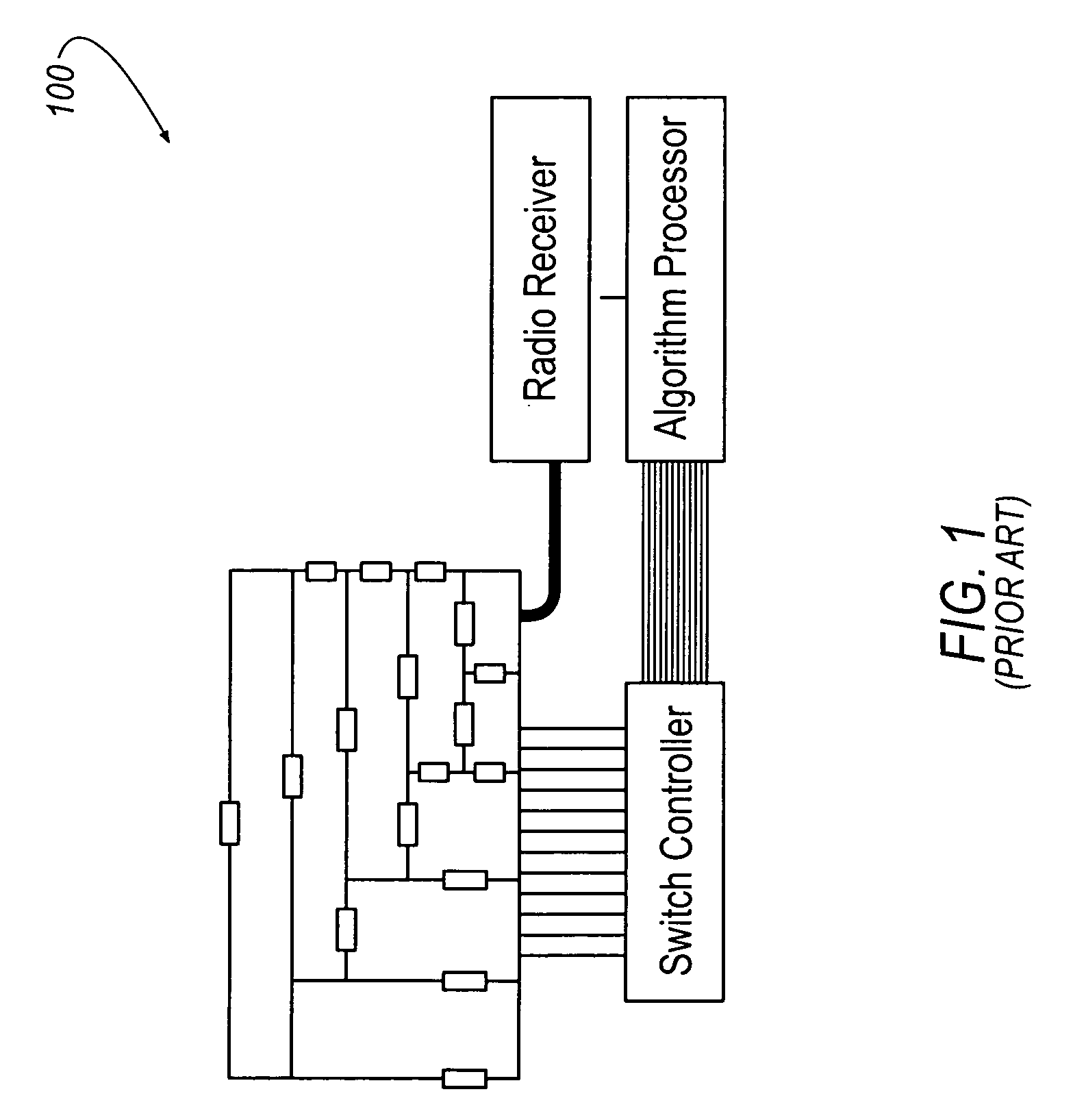
[0019] Referring generally to FIGS. 3-6H, the above described disadvantages are overcome and a number of advantages are realized by an inventive frequency-selective-surface (FSS) seen generally at reference numerals 300, 400, and 500 in FIGS. 3-5, respectively. As described in greater detail below, the FSS 300, 400, 500 is designed to change radio frequency (RF) surface characteristics in response to antenna characteristics and other environmental conditions. To achieve this, the FSS 300, 400, 500 incorporates a self-structuring capability in response to the operating characteristics of an antenna 302, 402, 502 and / or the environmental conditions. Accordingly, the FSS 300, 400, 500 is hereinafter referred to as a “self-structuring frequency selective surface” (SSFSS) 300, 400, 500. As opposed to the '723 patent, which teaches a self-structuring antenna (SSA) including a plurality of individual elements connected by switches to re-shape an antenna for reception of desired frequencies...


PUM


Abstract

An antenna system is disclosed. The antenna system includes at least one antenna element and an adaptable frequency-selective-surface responsive to operating characteristics of the at least one antenna element and/or surrounding environmental conditions

Description

RELATED APPLICATIONS [0001] This application contains subject matter related to co-pending application Attorney Docket Number DP-309795 / U.S. application Ser. No. XX / XXX,XXX filed Month, Date, YEAR.TECHNICAL FIELD [0002] The present invention generally relates to frequency selective surfaces and, more particularly, to dynamically adjustable frequency selective surfaces. BACKGROUND OF THE INVENTION [0003] Automotive vehicles are commonly equipped with audio radios that receive and process signals relating to amplitude modulation / frequency modulation (AM / FM) antennas, satellite digital audio radio systems (SDARS) antennas, global positioning system (GPS) antennas, digital audio broadcast (DAB) antennas, dual-band personal communication systems digital / analog mobile phone service (PCS / AMPS) antennas, Remote Keyless Entry (RKE) antennas, Tire Pressure Monitoring System (TPM) antennas, and other wireless systems. [0004] SDARS, for example, offer digital radio service covering a large geog...

Claims


Application Information

Patent Timeline
Patent Type & Authority Applications(United States)
IPC IPC(8): H01Q3/24H01Q3/44H01Q3/46H01Q15/00H01Q21/06
CPCH01Q3/24H01Q3/44H01Q15/002H01Q21/061H01Q3/46
Inventor NAGY, LOUIS L.
Owner APTIV TECH LTD
Why Eureka
Try Eureka