Antenna array with asymmetric elements

a technology of asymmetric elements and antenna arrays, applied in the field of circular antenna arrays, can solve problems such as constructive interference and interference with rf coverag

Active Publication Date: 2015-05-07
SYMBOL TECH LLC
View PDF4 Cites 234 Cited by
  • Summary
  • Abstract
  • Description
  • Claims
  • Application Information

AI Technical Summary

Problems solved by technology

One factor that impairs RF coverage are the nulls that result from destructive interference caused by multipath fading.
On the other hand, multipath propagation can also result in constructive interference, which can improve RF coverage and the range of an RFID reader.
However, a large antenna is required in order to achieve high directivity, which may pose mounting problems and may be undesirable for an RFID reader, where the smaller the reader the better.

Method used


Image

  • Antenna array with asymmetric elements
  • Antenna array with asymmetric elements
  • Antenna array with asymmetric elements

Examples


Embodiment Construction

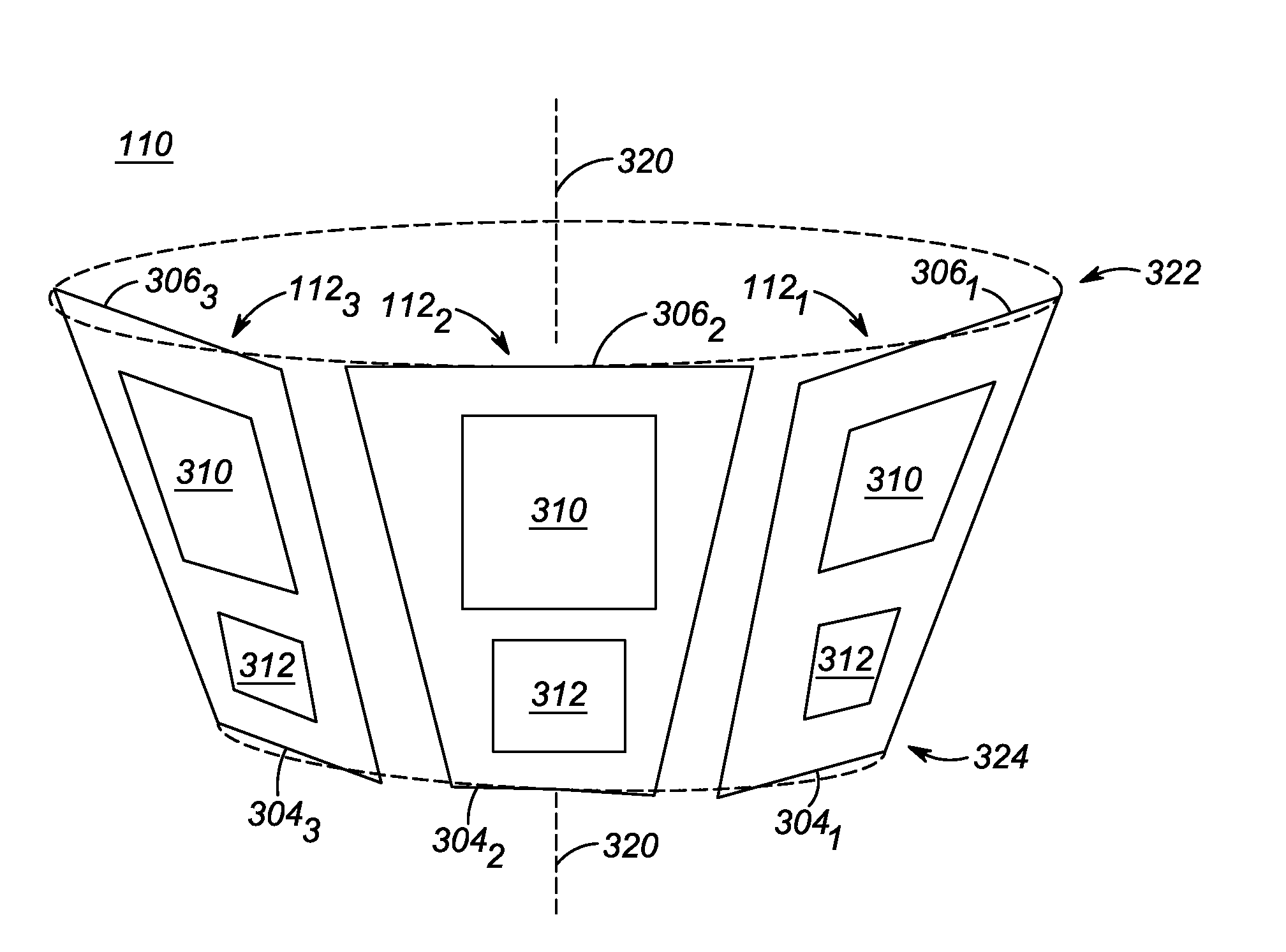
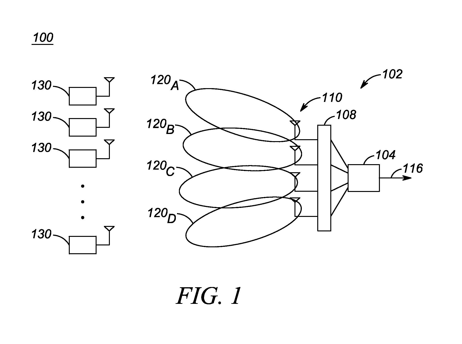
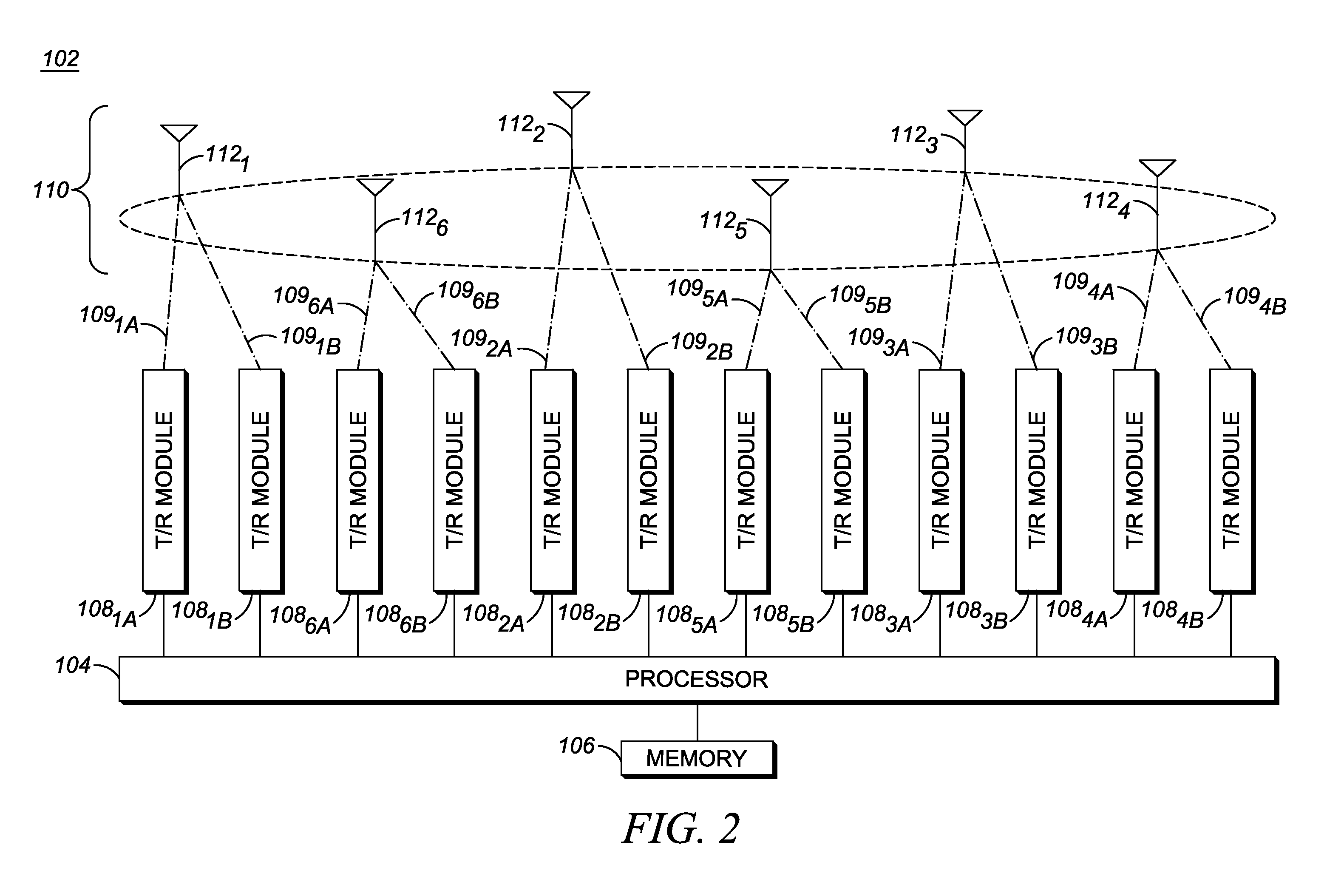
[0013]Accordingly, to address the need for a Radio Frequency Identification (RFID) reader capable of transmitting with high directivity, an antenna array is provided for an RFID reader, which antenna array includes multiple antenna elements circumferentially distributed around a longitudinal axis of the antenna array. Each antenna element includes multiple patch elements disposed above one or more underlying substrates and wherein the multiple patch elements of each antenna element are disposed on an outer side of the antenna element. Further, one or more of the antenna elements is an asymmetric antenna element, wherein a first end of the asymmetric antenna element is wider than a second, opposite end of the asymmetric antenna element, wherein a first patch element disposed proximate to the first end of the asymmetric antenna element is larger than a second patch element disposed proximate to the second end of the asymmetric antenna element, and wherein a resonant frequency associat...


PUM


Abstract

An RFID reader is provided that includes an antenna array comprising multiple antenna elements circumferentially distributed around a longitudinal axis of the antenna array. Each antenna element includes multiple patch elements disposed above one or more underlying substrates, wherein the patch elements of each antenna element are disposed on an outer side of the antenna element. Further, one or more of the antenna elements is an asymmetric antenna element, wherein a first end of the asymmetric antenna element is wider than a second, opposite end of the asymmetric antenna element, wherein a first patch element disposed proximate to the first end of the asymmetric antenna element is larger than a second patch element disposed proximate to the second end of the asymmetric antenna element, and wherein a resonant frequency associated with the first patch element is approximately the same as a resonant frequency associated with the second patch element.

Description

FIELD OF THE INVENTION[0001]The present invention relates to wireless communication systems and, more particularly, to a circular antenna array used in a wireless communication system.BACKGROUND OF THE INVENTION[0002]Radio Frequency (RF) coverage is an important consideration in the deployment of Radio Frequency Identification (RFID) systems. One factor that impairs RF coverage are the nulls that result from destructive interference caused by multipath fading. On the other hand, multipath propagation can also result in constructive interference, which can improve RF coverage and the range of an RFID reader.[0003]RFID readers that employ beam steering techniques using phase array antennas typically have better RF coverage than RFID readers that use traditional antennas due to the phase array antennas' ability to steer a beam and thereby mitigate fading due to multipath. Correspondingly, the better the directivity of an antenna, the better the ability of the antenna to mitigate fading...

Claims


Application Information

Patent Timeline
Patent Type & Authority Applications(United States)
IPC IPC(8): G06K7/10H01Q21/00H01Q21/08H01Q21/20
CPCG06K7/10356H01Q21/08H01Q21/0006H01Q21/205H01Q9/0435H01Q9/0442H01Q19/021H01Q21/20G06K7/10326H01Q1/2216H01Q1/50H01Q9/0407H01Q9/0428
Inventor KOCH, MICHAEL J.
Owner SYMBOL TECH LLC
Why Eureka
Try Eureka