
Nanostructure lithium titanate electrode for high cycle rate rechargeable electrochemical cell

a lithium titanate electrode, high cycle rate technology, applied in the direction of lithium compounds, alkali titanates, cell components, etc., can solve the problems of significant loss detriment to the ultimate operation of rechargeable cell devices, and detriment to the effect of electrochemical cell capacity loss

Inactive Publication Date: 2007-05-01
RUTGERS THE STATE UNIV
View PDF8 Cites 79 Cited by
  • Summary
  • Abstract
  • Description
  • Claims
  • Application Information

AI Technical Summary

Benefits of technology

The present invention provides a process for synthesizing lithium titanate with nanostructure dimensions, which can be used as a zero-strain active electrode material for rechargeable electrochemical cells. The process involves heating a mixture of precursors containing nano-sized TiO2 and a thermolabile compound, such as LiOH or Li2CO3, to a high temperature and holding it for a short time to form Li4Ti5O12 nanoparticles. The resulting nanoparticles have a high specific energy storage capacity and can operate at high recharge rates. The synthesized material can be dispersed in a binder, plasticizer, and adjunct components to form an electrode member for use in rechargeable electrochemical cells. The cells have high recharge capacity and low capacity loss over a long period of cycling.

Problems solved by technology

However, even while performing significantly well in high capacity recycling electrical storage systems, many of these materials exhibit detrimental properties which detract from the ultimate operation of rechargeable cell devices.
While the relatively minute size of Li+ ions, as compared to other mobile ion species of varying efficacy, minimizes to a great extent the physical strain upon the electrode material structure, there nonetheless often results from repetitive cycling effects a significant loss of electrochemical cell capacity, whether due to internal disruption of electrical continuity within the structure of the active compound or otherwise.
Such long charging periods are, unfortunately, impractical and unacceptable in the marketplace.

Method used


Image

  • Nanostructure lithium titanate electrode for high cycle rate rechargeable electrochemical cell
  • Nanostructure lithium titanate electrode for high cycle rate rechargeable electrochemical cell
  • Nanostructure lithium titanate electrode for high cycle rate rechargeable electrochemical cell

Examples


example i

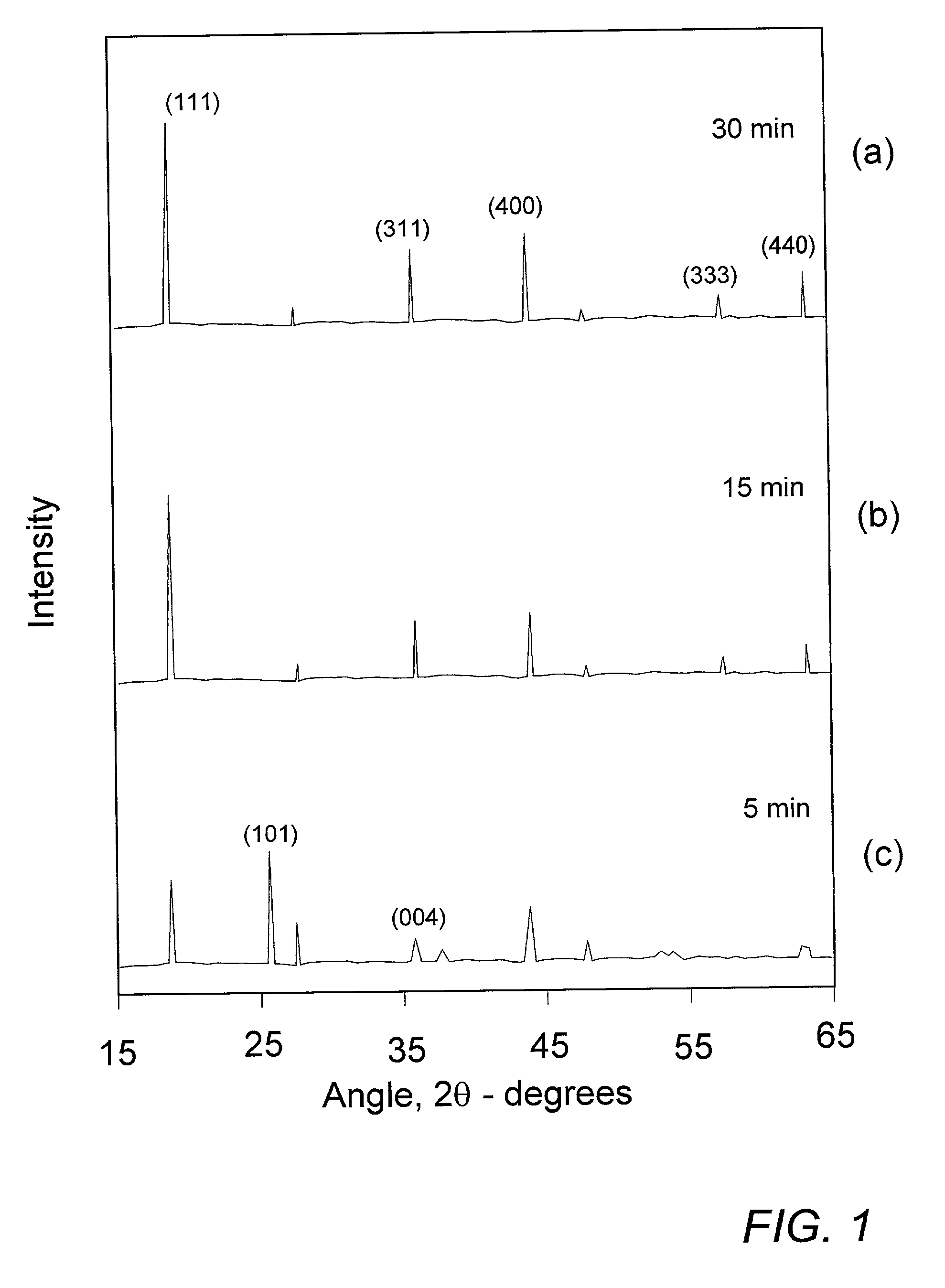
[0026]The determination of minimum annealing time for sufficient reaction of mixed precursor compounds was effected in the following manner. 40.0 g of commercial nanostructure TiO2 (30–50 nm) was dry-milled with 14.8 g of Li2CO3 to obtain an homogeneous master batch of precursor mixture. Sample portions of about 2 g of the master mix were successively utilized by distributing the powder as a layer of about 10 mm thickness in the bottom of an alumina crucible and inserting the crucible into an oven preheated to about 750–800° C. Each subsequent sample was allowed to remain in the oven for a decreasing predetermined time before being removed and allowed to immediately cool to room temperature, thereby essentially quenching the sample and preventing further reaction. The resulting Li4Ti5O12 reaction product was then examined by standard CuKαx-ray diffraction (XRD) to ascertain whether the applied annealing time were sufficient to ensure complete reaction of the mixed precursors.

[0027]S...

example ii

[0030]As seen in FIG. 3, a battery test cell structure 30 comprises a positive electrode member 33, a negative electrode member 37, and an interposed separator member 35 containing cell electrolyte. Current collector members 31, 39 associated with the respective positive and negative electrode members provide points of electrical circuit contact for the cell.

[0031]Typically, positive electrode 33 comprises a vinylidene copolymer matrix membrane in which is dispersed the Li4Ti5O12 test material, while negative counter-electrode 37 comprises a similar copolymer matrix dispersion of an active material compound, or simply an active metal foil, capable of reversibly plating, alloying, intercalating, or otherwise providing a source of lithium ions. Separator 35 may likewise be a polymeric membrane, as described in the referenced specification, or it may comprise a widely used microporous membrane or simply a glass fiber mat, any of which is capable of retaining the non-aqueous electrolyte...

example iii

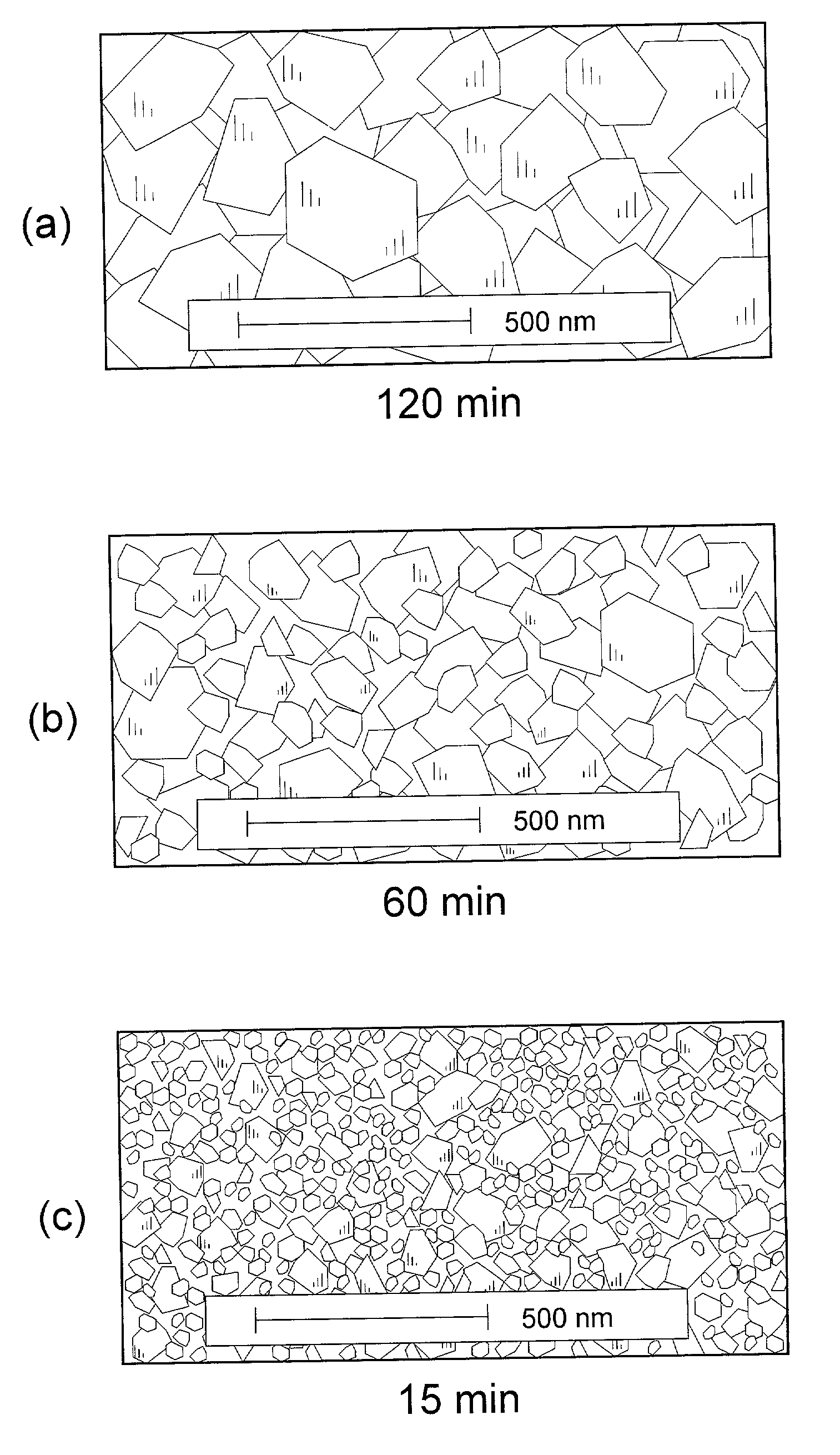
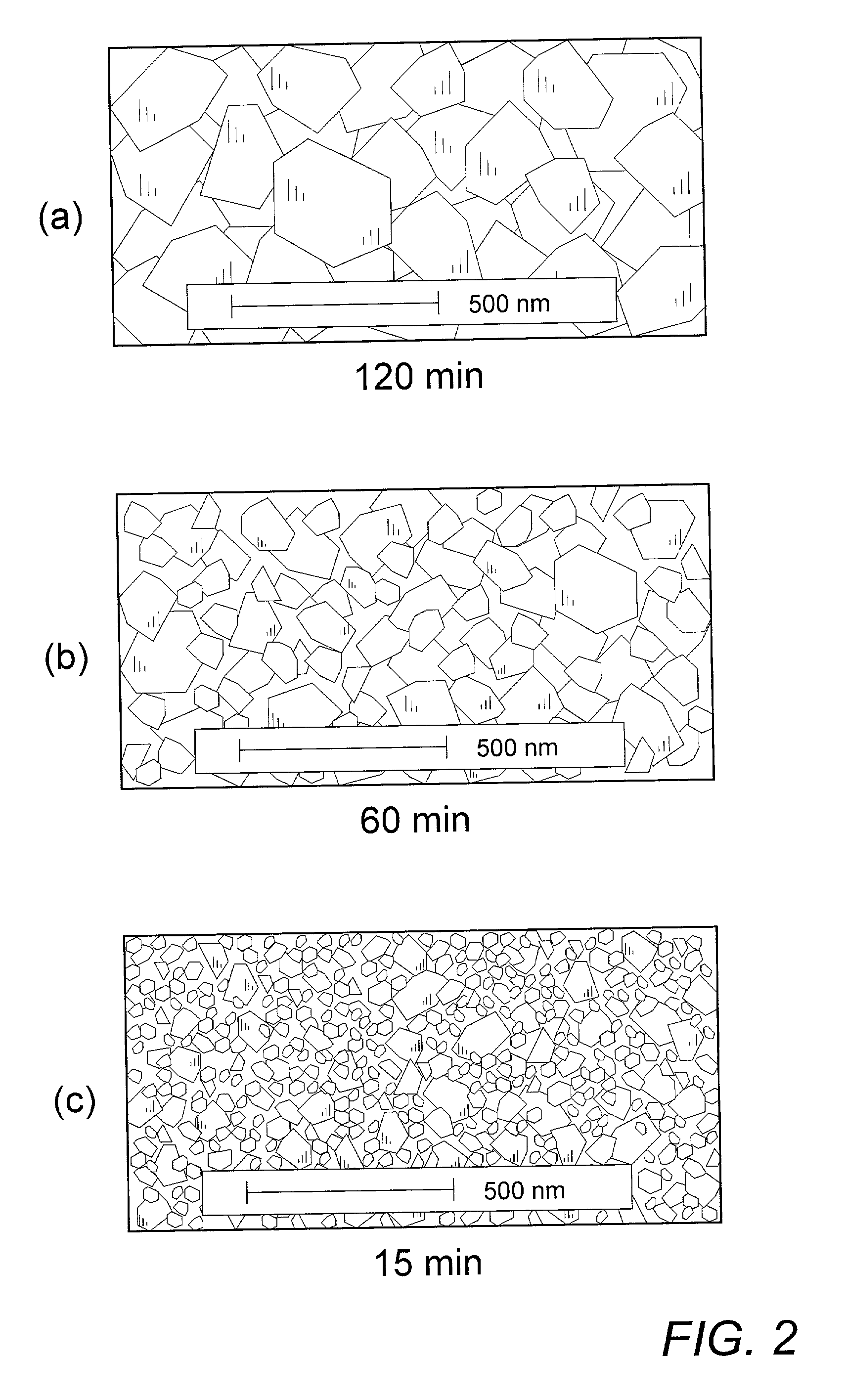
[0035]Similar series of test cells were cycled at varying increased rates of 1C, 5C, and 10C to determine the effect of Li4Ti5O12 particle size on the ability of a cell to exhibit stable high capacity levels while cycling at such higher rates. The resulting data were plotted as indication of the degree of initial capacity, as determined in Example II, which each active material sample of increasingly long anneal time, and thus larger particle size, was capable of maintaining as input current density increased, and thus intercalation time decreased. The plots of such data shown in FIG. 5 indicate the superior capacity retention of the preferred, smaller particle Li4Ti5O12 materials obtained from annealing times in the range of 15–30 min. The unsatisfactory performance of materials prepared by annealing in excess of about 8 h in accordance with the above-noted practices of the prior art are particularly apparent.


PUM

PropertyMeasurementUnit
particle sizeaaaaaaaaaa
particle sizesaaaaaaaaaa
temperatureaaaaaaaaaa

Abstract

Rechargeable electrochemical cells, such as lithium batteries and asymmetric hybrid battery / supercapacitor systems, exhibiting exceptional specific capacity levels and stability over extended high-rate recharge cycling comprise nanostructure zero strain Li4Ti5O12 intercalation electrode material synthesized in a short duration process of annealing mixed TiO2 and Li-source precursor compounds at about 800° C. for a time of about 15–30 min which is not substantially longer than that required to effect maximum available reaction between the precursors, thereby substantially eliminating the growth of synthesized Li4Ti5O12 particles beyond nanostructure size. The process reduces by order of magnitude the time and energy required for synthesis of the active electrode material and fabrication of utilizing cell devices, and provides such nanostructure material which enables repeated, high-rate recharge cycling without loss of cell capacity or efficiency.

Description

BACKGROUND OF THE INVENTION[0001]The present invention relates to rechargeable electrochemical energy storage systems, particularly to such systems comprising materials capable of reversibly taking up and releasing lithium ions as a means of storing and supplying electrical energy. More specifically, the invention relates to the synthesis and utilization of nanostructure lithium titanate as the active electrode component material of electrochemical cells capable of exhibiting high specific capacity at high recharge rates.[0002]During the course of development of rechargeable lithium ion cells and the like, numerous materials capable of reversibly accommodating lithium ions have been investigated. Among these, occlusion and intercalation materials, such a carbonaceous and graphitic compounds, and transitions metal oxide spinels, have proved to be particularly well-suited to such applications. However, even while performing significantly well in high capacity recycling electrical stor...

Claims


Application Information

Patent Timeline
Patent Type & Authority Patents(United States)
IPC IPC(8): H01M4/58C01D1/00C01D15/02C01D17/00H01M6/00C01G23/00H01M4/131H01M4/1391H01M4/48H01M4/485H01M10/052H01M10/36
CPCC01G23/005H01M4/131H01M4/485H01M4/5825H01M4/1391C01P2002/70C01P2006/40Y10T29/49108H01M10/052Y02E60/122Y02E60/10
Inventor AMATUCCI, GLENN G.
Owner RUTGERS THE STATE UNIV
Learn More