Reflector antenna system including a phased array antenna operable in multiple modes and related methods

a phased array, antenna technology, applied in the field of communications systems, can solve the problems of long change time, prone to failure, and large amount of time for antennas to change, and achieve the effect of reducing the need for signal amplification, and reducing the loss of signal

Inactive Publication Date: 2005-11-15
NORTH SOUTH HLDG
View PDF24 Cites 239 Cited by
  • Summary
  • Abstract
  • Description
  • Claims
  • Application Information

AI Technical Summary

Benefits of technology

[0016]Accordingly, because the phased array antenna has a feed-through zone, it advantageously allows the antenna beam to pass therethrough. As such, a relatively large phased array antenna may be placed in front of the at least one antenna reflector, yet without the large amount of blockage that would otherwise occur by similarly using a comparably sized prior art array antenna. Moreover, the feed device may advantageously be used for beam steering. As a result, large scan angles may be obtained without having to mount the at least one reflector on a movable platform, and without the phased array antenna having to electrically steer the beam over the entire scan angle, which results in less signal loss and therefore a reduced need for signal amplification by the phased array antenna.

Problems solved by technology

However, such antennas also have their drawbacks.
More particularly, the mechanical steering components may be relatively heavy and / or bulky for a large reflector, they take a relatively long amount of time to change directions, and they may be prone to failure.
Plus, to provide a large scan angle, the antenna system requires a large amount of clearance to move the reflector.
Yet, phased array antennas are typically more costly to implement than reflector antennas, and they tend to suffer greater signal loss as the scan angle increases.
While gain elements (i.e., amplifiers) and increased numbers of antenna elements can be used to offset such signal loss and achieve desired scan angles, this increases the footprint of the array, as well as its power consumption.
If the feed beamwidth is too wide, excess feed energy will spill over the edges of the reflector, reducing efficiency.
This is done because it is very difficult to design a reflector feed that only illuminates the reflector antenna.
That is, there will almost always be some amount of spillover and amplitude taper across the reflector due to the antenna pattern of the feed.
However, such implementations have been limited in their effectiveness.
That is, if the element array is placed in the path of the antenna beam, the array has to be relatively small (typically less than 10%–15% the diameter of the reflector it is feeding as a rule-of-thumb) or severe signal blockage will occur causing undesirable degradation of the resultant antenna pattern and gain.
Yet, a small array may not be sufficient to provide desired scan angles.
A disadvantage of such a system is that the required array size for large amounts of scan can be large and cause significant blockage.
Since typically the active region is much smaller than the entire array, the amount of blockage and subsequent performance loss is not acceptable in many applications and may indeed be so bad as to cause the system to not function at all.
Yet, one drawback of using such an arrangement is that a significant amount of scan angle may be given up by offsetting the feed array from the path of the antenna beam.

Method used


Image

  • Reflector antenna system including a phased array antenna operable in multiple modes and related methods
  • Reflector antenna system including a phased array antenna operable in multiple modes and related methods
  • Reflector antenna system including a phased array antenna operable in multiple modes and related methods

Examples


Embodiment Construction

[0031]The present invention will now be described more fully hereinafter with reference to the accompanying drawings, in which preferred embodiments of the invention are shown. This invention may, however, be embodied in many different forms and should not be construed as limited to the embodiments set forth herein. Rather, these embodiments are provided so that this disclosure will be thorough and complete, and will fully convey the scope of the invention to those skilled in the art. Like numbers refer to like elements throughout, and prime and multiple prime notation are used to indicate similar elements in alternate embodiments.

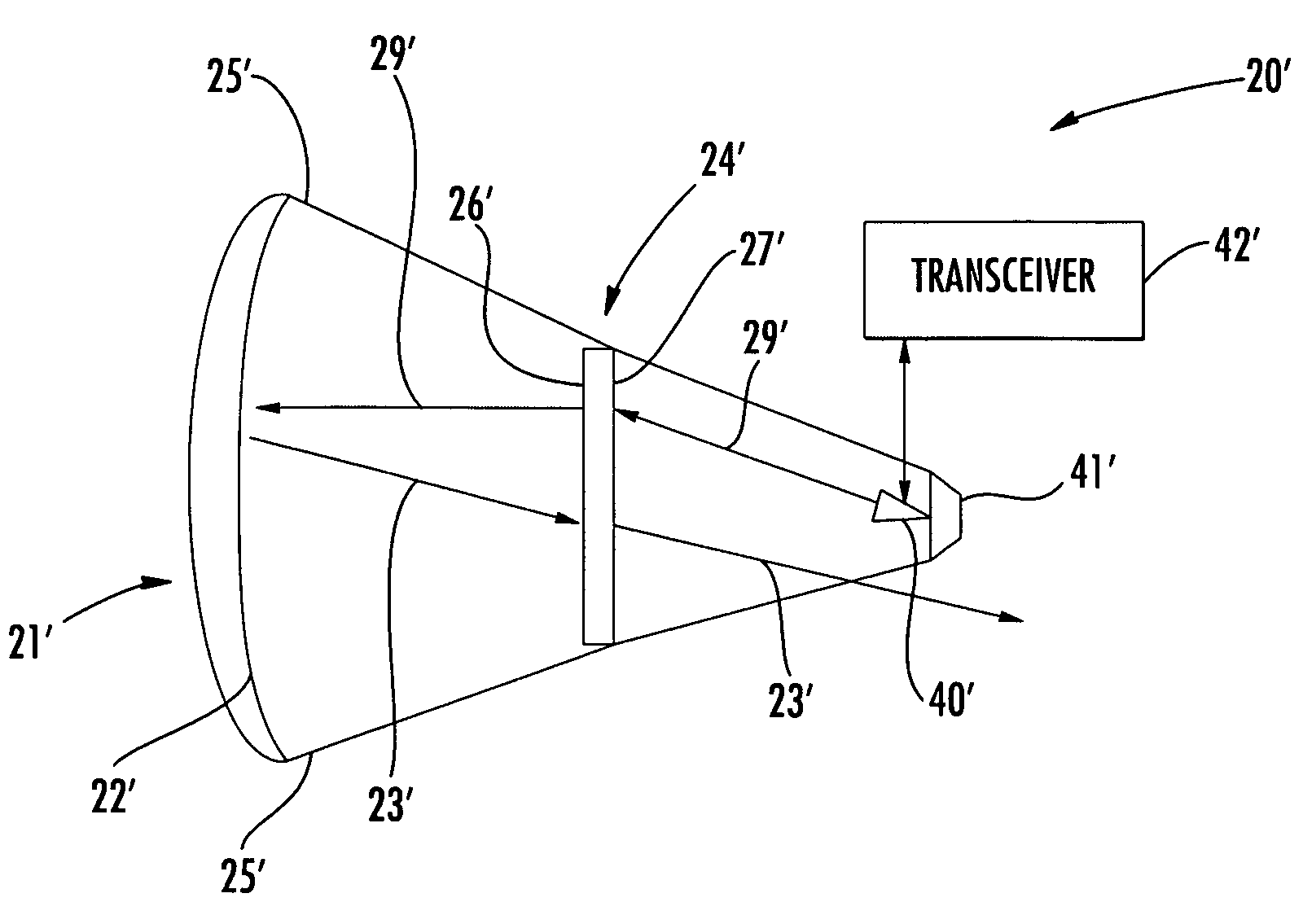
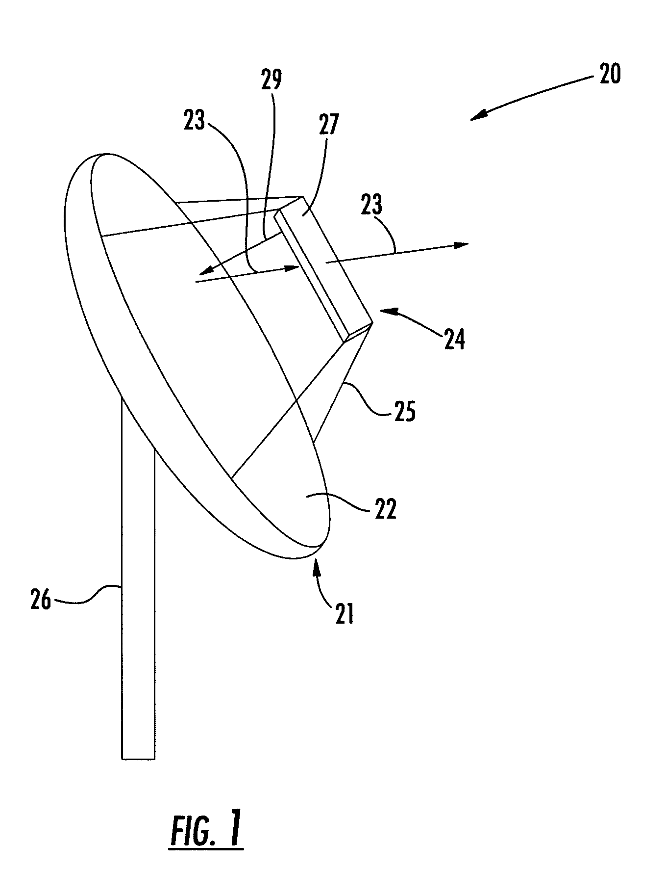
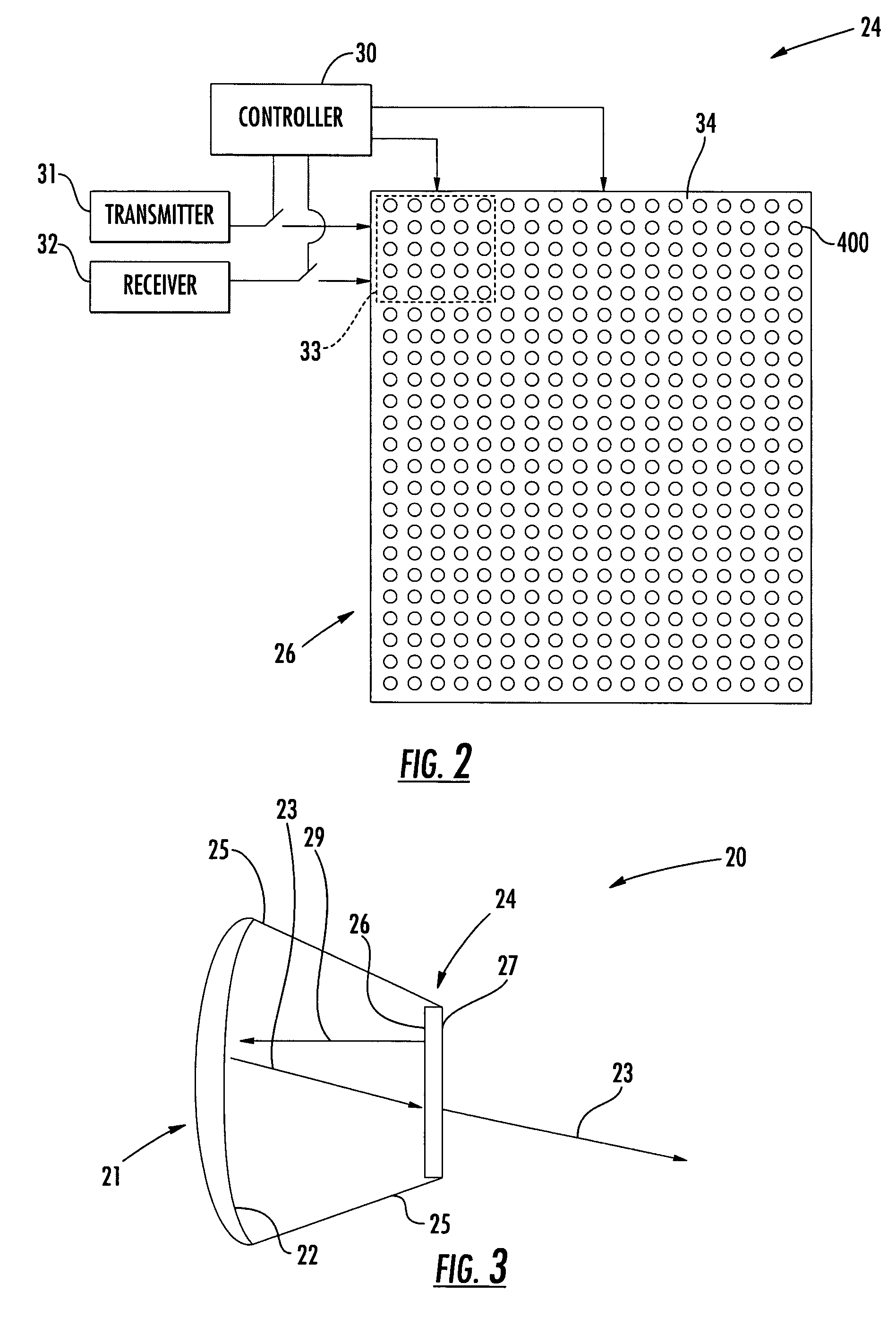
[0032]Referring initially to FIGS. 1 through 4, a first embodiment of a reflector antenna system 20 in accordance with the present invention is now described. The system 20 illustratively includes an antenna reflector 21 having an arcuate reflecting surface 22 for defining an antenna beam 23, as will be appreciated by those skilled in the art. Furthermore,...


PUM


Abstract

A reflector antenna system may include at least one antenna reflector having an arcuate shape and defining an antenna beam, a feed device spaced apart from the at least one antenna reflector, and a phased array antenna positioned in the antenna beam between the at least one antenna reflector and the feed device. More particularly, the phased array antenna may include a substrate and a plurality of back-to-back pairs of first antenna elements carried by the substrate and configured for defining at least one feed-through zone for the antenna beam. The phased array antenna may further include a plurality of back-to-back pairs of second antenna elements carried by the substrate and defining at least one active beamsteering zone for the antenna beam.

Description

FIELD OF THE INVENTION[0001]The present invention relates to the field of communications systems, and, more particularly, to antenna systems and related methods.BACKGROUND OF THE INVENTION[0002]Steerable antennas are used in a variety of applications where transmissions are to be directed at different geographical locations or targets, or conversely where it is desirable to receive signals only from a particular direction. Perhaps the two most common types of steerable antennas are reflector antennas and phased array antennas. Reflector antennas include a reflector and a feed device, such as a horn, positioned at the focal length of the reflector. The reflector is mounted on a mechanical steering device, such as a gimbal, which directs the reflector at the intended target.[0003]Reflector antenna systems have certain advantages. For example, they are relatively inexpensive, and they can achieve a fairly large scan angle. However, such antennas also have their drawbacks. More particul...

Claims


Application Information

Patent Timeline
Patent Type & Authority Patents(United States)
IPC IPC(8): H01Q15/00H01Q15/02H01Q3/26H01Q3/44H01Q3/46H01Q15/14H01Q19/00H01Q19/06H01Q21/00H01Q21/06
CPCH01Q3/26H01Q3/44H01Q3/46H01Q15/02H01Q15/148H01Q19/00H01Q19/062H01Q21/0018H01Q21/062H01Q15/0026
Inventor DURHAM, TIMOTHY E.RAWNICK, JAMES J.
Owner NORTH SOUTH HLDG
Why Eureka
Try Eureka