Rearward pedal movement restraint assembly for vehicle

a rearward-moving and seat-mounted technology, applied in mechanical control devices, instruments, tractors, etc., can solve the problems of increasing cost and mass, unable to apply devices to vehicles in which the knee airbag module is mounted high in the vehicle, etc., to reduce the number of components and avoid the increase in cost and mass, the effect of restricting the rearward movement of the pedal

Active Publication Date: 2014-04-01
TOYOTA JIDOSHA KK
View PDF29 Cites 0 Cited by
  • Summary
  • Abstract
  • Description
  • Claims
  • Application Information

AI Technical Summary

Benefits of technology

[0009]The invention provides a vehicular rearward pedal movement restraint assembly that may be installed in a vehicle in which the knee airbag module is mounted high, without increasing the number of component parts and cost.
[0011]Due to the foregoing construction, the pedal that moves rearward movement of the pedal caused by the impact of the frontal collision pivots toward the front of the vehicle, and therefore the amount of rearward movement of the pedal is reduced. Thus, due to the contact of the front end portion of the knee panel with the pedal, even when the foregoing aspect of the invention is applied to a vehicle in which the mount position of the knee airbag module is high, the amount of rearward movement of the pedal can be reduced by disposing the front end portion of the knee panel substantially at the same height as the intermediate portion of the pedal. Moreover, because the knee panel that protects the knees of the occupant at the time of the frontal collision of the vehicle is also used as a component part that restraint the rearward movement of the pedal, it is possible to avoid increases in the number of component parts and in cost and mass.
[0013]In the foregoing rearward pedal movement restraint assembly, the upper bracket plastically deforms by load that is transmitted to the knee panel by the knees of the occupant. On the other hand, the lower bracket has such a rigidity as to support the reaction force caused by the deployment of the knee airbag. That is, the lower bracket is made less easily deformable than the upper bracket, and the lower bracket is fixed to or near the front end portion of the knee panel (i.e., an end portion thereof that contacts the intermediate portion of the pedal). Therefore, the load transmitted (input) from the intermediate portion of the pedal to the front end portion of the knee panel can be supported by the high-rigidity lower bracket that is less easily deformable, so that rearward movement of the pedal can be effectively restrained.
[0015]In the foregoing structure, because the fastening portion between the knee airbag module and the knee panel is provided in the front end portion of the knee panel, the rigidity of the front end portion of the knee panel improves. Therefore, the deformation of the knee panel occurring when the intermediate portion of the pedal contacts the front end portion of the knee panel can be restrained, so that the rearward movement of the pedal can be effectively restrained.
[0017]According to the foregoing structure, if the intermediate portion of the pedal moving rearward deviates from the front end portion of the knee panel when the frontal collision of the vehicle occurs and the intermediate portion of the pedal impacts the front end portion of the knee panel, the intermediate portion of the pedal is displaced outward in the seat widthwise direction along a curvature or inclination of the front end portion of the knee panel. Therefore, approach of the pedal to the occupant can be avoided.
[0022]As described above, in the rearward pedal movement restraint assembly of the foregoing aspect of the invention is applicable also to a vehicle in which the mount position of the knee airbag module is high, and is able to avoid increases in the number of component parts and in cost and mass.

Problems solved by technology

However, in the knee airbag device of JP-A-2004-098868, because the device is constructed so that rearward movement of the pedal results in contact with an intermediate portion of the knee panel in an up-down direction, the device cannot be applied to vehicles in which the knee airbag module is mounted high in the vehicle.
Besides, in a vehicle having the body floor portion that is greatly accelerated at the time of a collision, there is a need to reinforce a rearward movement prevention bracket, which results in an increase in cost and mass.

Method used


Image

  • Rearward pedal movement restraint assembly for vehicle
  • Rearward pedal movement restraint assembly for vehicle
  • Rearward pedal movement restraint assembly for vehicle

Examples


Embodiment Construction

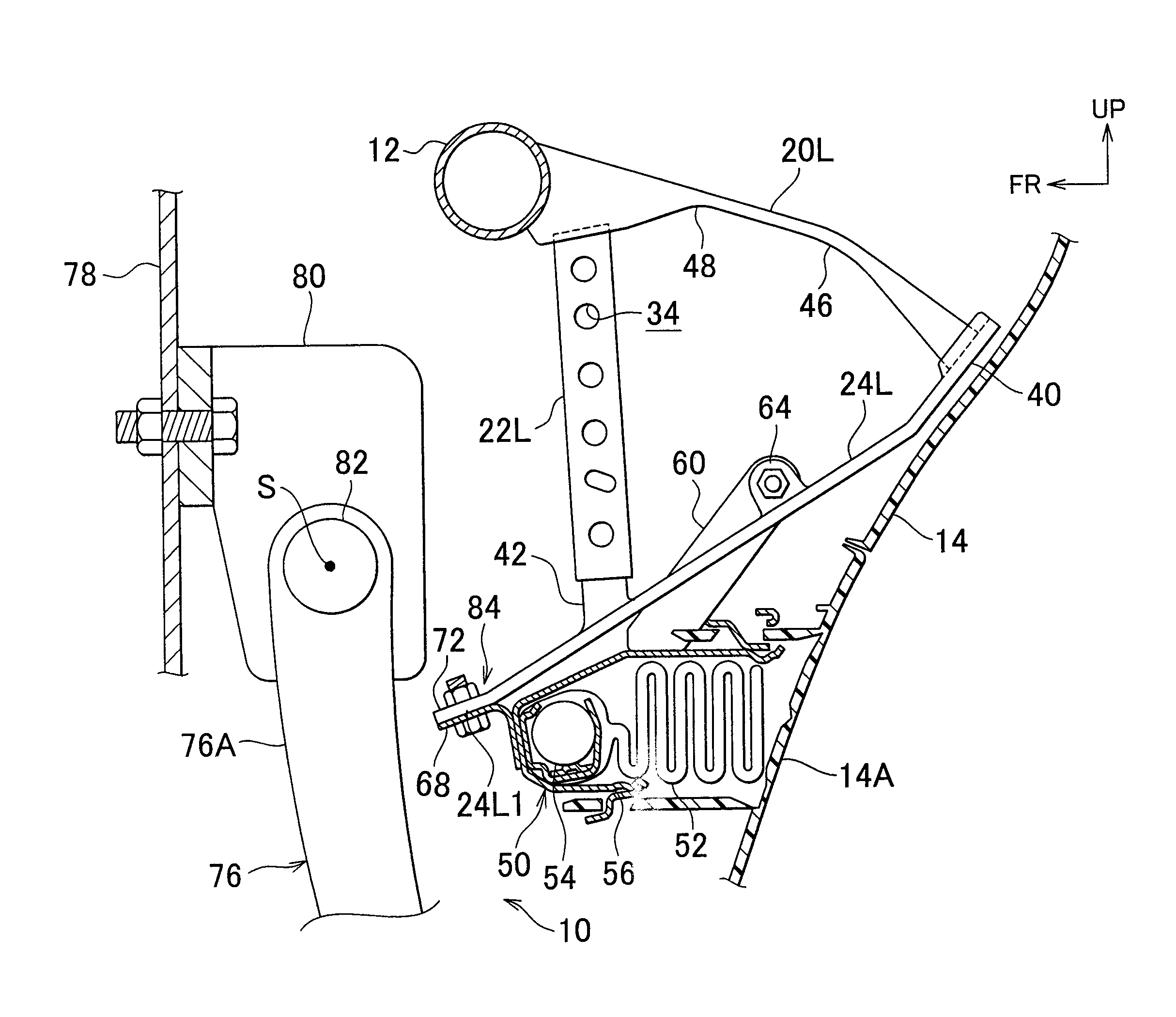
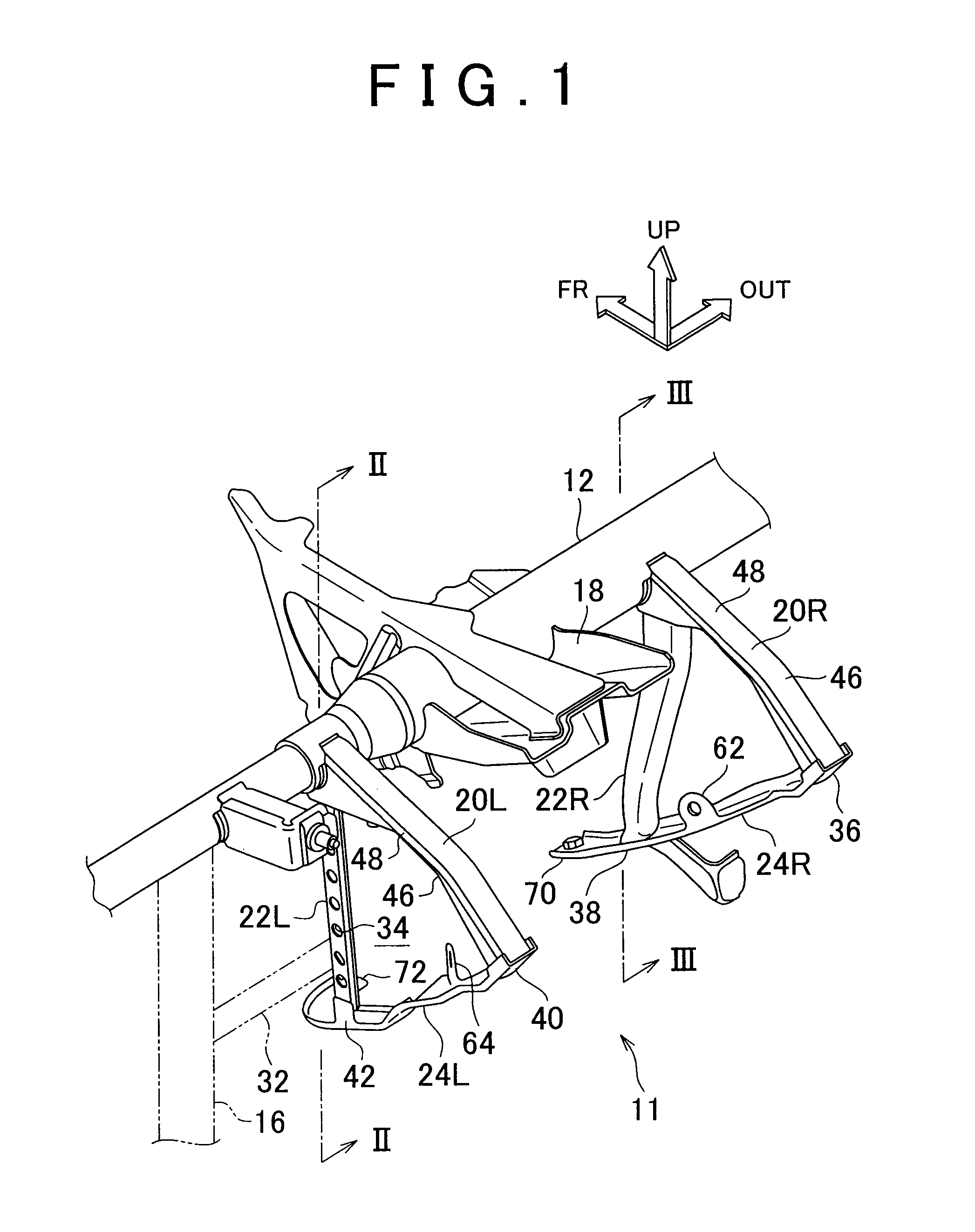
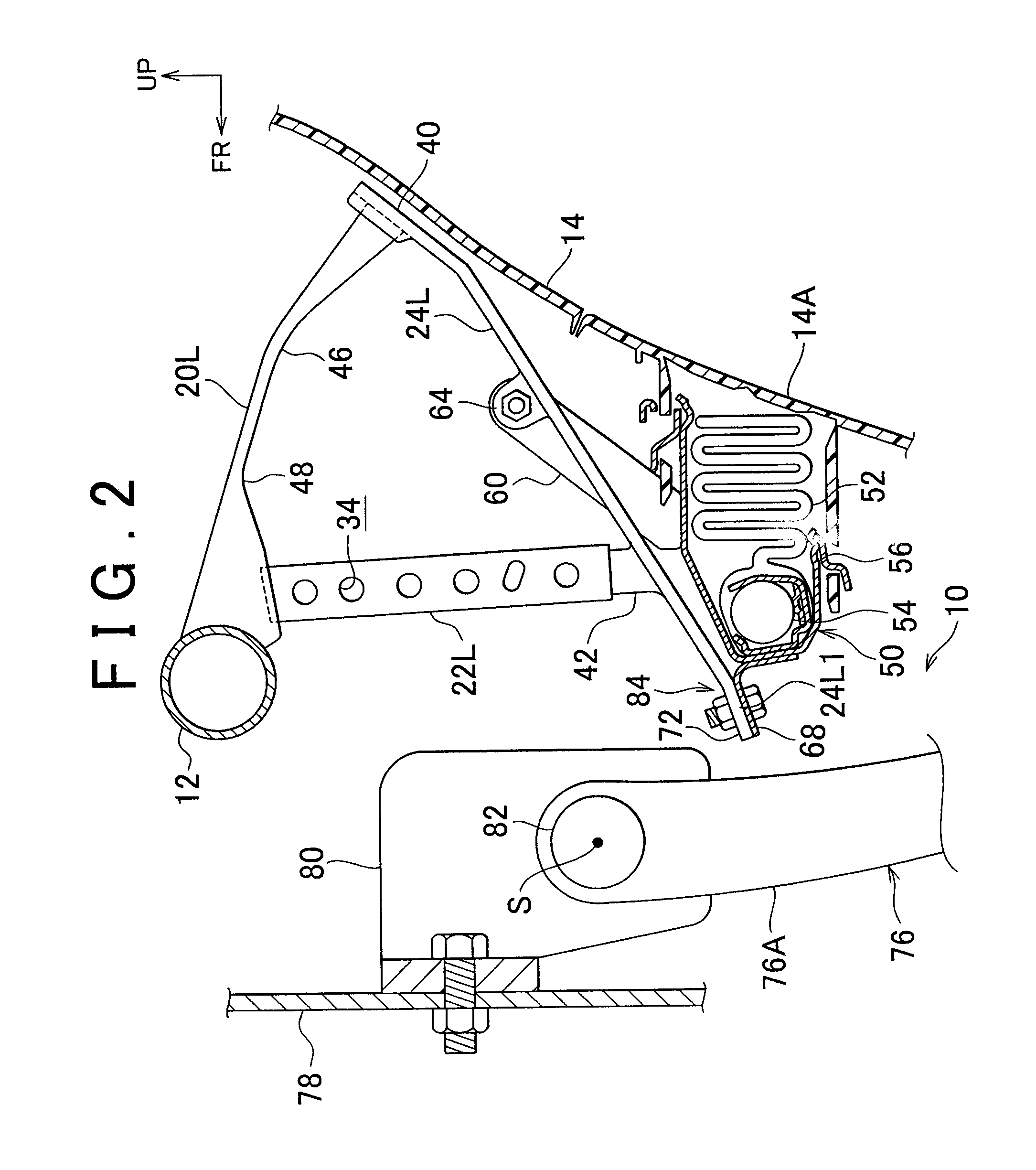
[0033]Hereinafter, with reference to FIG. 1 to FIG. 6, a rearward pedal movement restraint assembly 10 in accordance with a first embodiment of the invention will be described. In the drawings, the arrow FR shows a vehicle forward direction, and the arrow UP shows a vehicle's upward direction, and the arrow OUT shows a transverse outward direction.

[0034]A vehicle occupant knee protection device 11 is equipped with the rearward pedal movement restraint assembly 10 in accordance with the first embodiment. The vehicle occupant knee protection device 11 protects the knees of an occupant seated in the driver's seat of a right-hand-drive vehicle, that is, a vehicle with its steering wheel disposed on the right side. As shown in FIGS. 1 to 3, the vehicle occupant knee protection device 11 is attached to an instrument panel reinforcement 12 as shown in FIGS. 1 and 3. The instrument panel reinforcement 12 is disposed at an inner side of an instrument panel 14 that is provided at the front of...


PUM


Abstract

In a rearward pedal movement restraint assembly for a vehicle, an intermediate portion of a clutch pedal, which moves rearward by the impact of a frontal collision of the vehicle when the frontal collision occurs, contacts a forward portion of a knee panel so that the clutch pedal pivots toward the front of the vehicle so that the amount of rearward movement of the clutch pedal is reduced.

Description

INCORPORATION BY REFERENCE[0001]The disclosure of Japanese Patent Application No. 2010-221753 filed on Sep. 30, 2011 including the specification, drawings and abstract is incorporated herein by reference in its entirety.BACKGROUND OF THE INVENTION[0002]1. Field of the Invention[0003]The invention relates to a rearward pedal movement restraint assembly that restrains the rearward movement of a pedal when a frontal collision occurs in a vehicle.[0004]2. Description of Related Art[0005]In a knee airbag device shown in Japanese Patent Application Publication No. 2004-098868 (JP-A-2004-098868), a knee panel, which contacts a brake pedal to stop the rearward movement of the pedal in the event of a collision, is integrally formed in the front end of a knee airbag module.[0006]In a rearward movement prevention structure for a pedal shown in Japanese Patent Application Publication No. 2007-084009 (JP-A-2007-084009), an electric power steering unit is provided with a rearward movement prevent...

Claims


Application Information

Patent Timeline
Patent Type & Authority Patents(United States)
IPC IPC(8): G05G1/32B60R21/09B60T7/06
CPCB60R21/09G05G1/32B60T7/065B62D25/145B60R2021/0051Y10T74/20888
Inventor FUJIWARA, YUSUKE
Owner TOYOTA JIDOSHA KK
Why Eureka
Try Eureka