Variable stroke engine

a technology of internal combustion engine and variable stroke, which is applied in the direction of auxilary lubrication, pressure lubrication, lubrication elements, etc., can solve the problems of significant increase in engine weight and overall increase in frictional loss, and achieve the effect of reducing vibrations without increasing engine weight, minimizing overall engine vibration, and reducing engine vibrations

Inactive Publication Date: 2010-03-04
HONDA MOTOR CO LTD
View PDF3 Cites 18 Cited by
  • Summary
  • Abstract
  • Description
  • Claims
  • Application Information

AI Technical Summary

Benefits of technology

[0020]According to a certain aspect of the present invention, the present invention also provides a variable stroke engine comprising a piston stroke varying mechanism including a plurality of links wherein the engine includes a plurality of cylinders, and link geometries of two of the cylinders that have pistons operating at mutually different phase relationships differ from each other. Thereby, the variable stroke engine can be configured to adequately reduce vibrations without increasing the weight of the engine.
[0021]According to this arrangement of the present invention, because the phases of the vibrations caused by the movements of the links can be shifted from one cylinder to another while the different cylinders have pistons operating in mutually different phases, it is possible to minimize the vibrations of the overall engine even without using a vibration reducing device such as a balancer shaft. Therefore, the vibrations of the engine can be reduced without increasing the number of components parts, weight and manufacturing cost of the engine, and this significantly contributes to the further weight reduction and cost reduction of the engine.

Problems solved by technology

This causes a significant increase in the weight of the engine.
If the link geometry is configured such that the angle φ remains small during the interval between the top dead center and the point of the maximum piston speed, the maximum inclination angle of the upper link φmax (absolute value) inevitably increases, and this results in an overall increase in the frictional loss.

Method used


Image

  • Variable stroke engine
  • Variable stroke engine
  • Variable stroke engine

Examples


Embodiment Construction

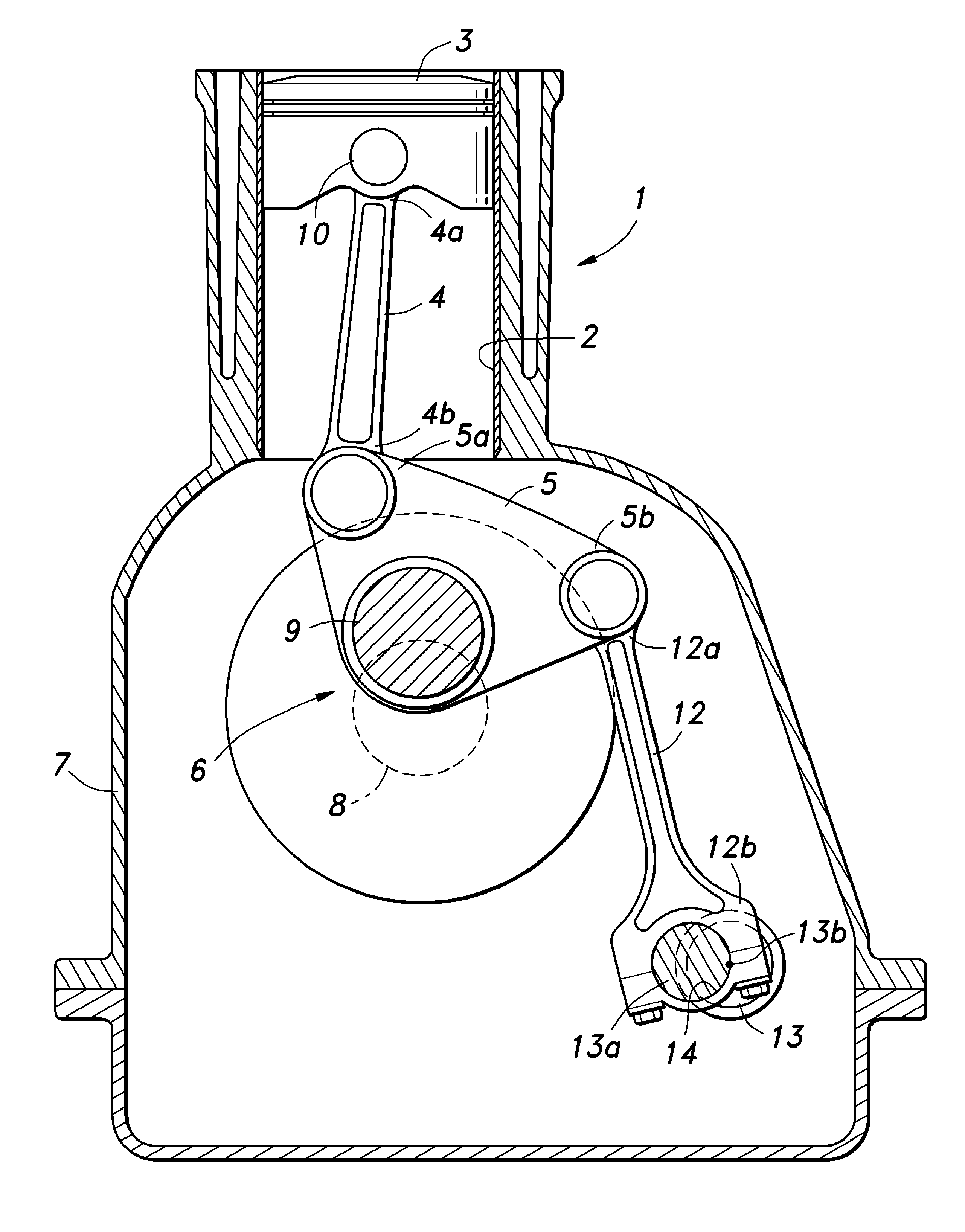
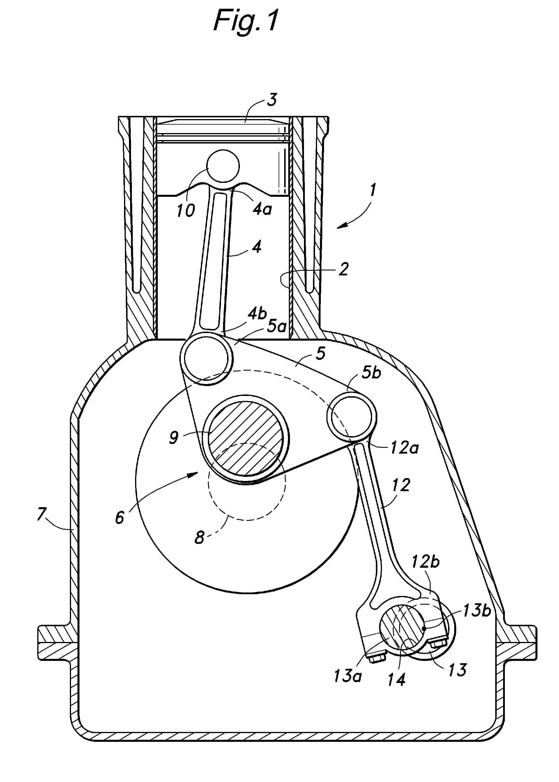
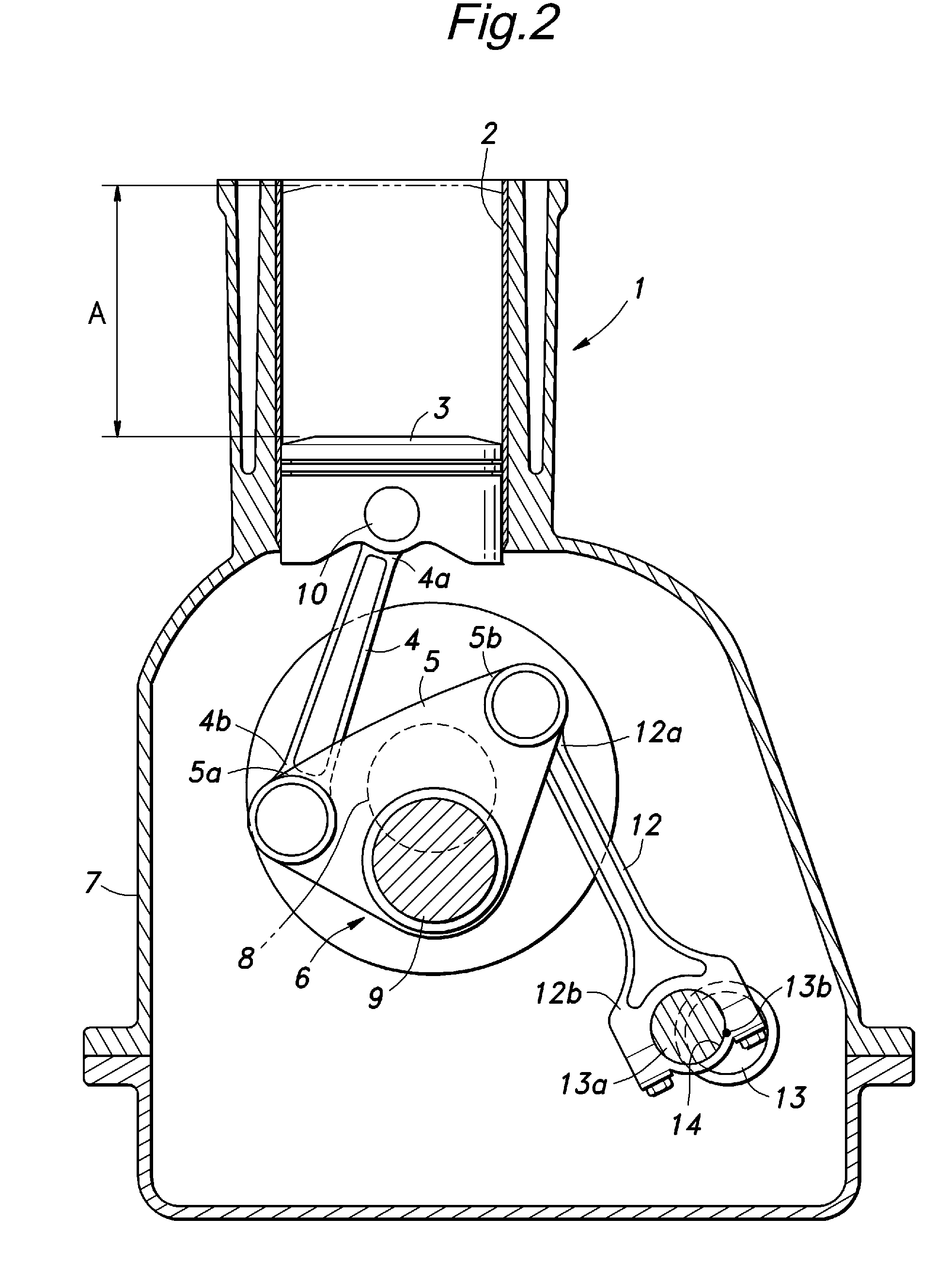
[0022]FIGS. 1 to 4 are simplified views of a variable compression ratio / displacement engine 1 given as an embodiment of the variable stroke engine of the present invention with an upper part thereof such as a cylinder head omitted from the drawings. A piston 3 that is slidably received in a cylinder 2 of the engine 1 is connected to a crankshaft 6 via a pair of links consisting of a first link 4 and a second link 5. The valve actuating mechanism, exhaust system and intake system of this engine may be similar to those of conventional four-stroke engines.

[0023]The crankshaft 6 is essentially identical to that of a conventional fixed compression ratio engine, and comprises a crank journal 8 (rotational center of the crankshaft 6) supported in a crankcase and a crankpin 9 which is radially offset from the crank journal 8. The second link 5 is triangular in shape, and an intermediate point (first vertex) of the second link 5 is supported by the crankpin 9 so as to be able to tilt like a ...


PUM


Abstract

In a variable stroke internal combustion engine, by determining the relationships of a connecting point (D) between a first link (4) and second link (5) and a connecting point (B) between the second link (5) and a control link (12) with respect to a center (A) of a crankpin (9) to be such that ΔD<ΔB holds over an entire rotational angle of the crankshaft, where ΔD is the distance between D and A and ΔB is the distance between B and A, an adequate durability of the engine can be ensured without increasing the weight thereof.

Description

TECHNICAL FIELD[0001]The present invention relates to a variable stroke internal combustion engine, and in particular to a variable stroke engine that can minimize the load acting on the control link during the expansion stroke of the engine.BACKGROUND OF THE INVENTION[0002]A variable stroke engine known from Japanese Patent Laid Open Publication No. 2001-317383 comprises an upper connecting rod 4 (first link) and a lower connecting rod 7 (second link) that connect a piston 9 with a crankshaft 10, and a swing arm 8 (control link) that connects the lower connecting rod with a shaft 11 (control shaft) having an eccentric portion and supported by an engine main body, and the piston stroke can be varied by changing the connecting point between the swing arm and engine main body.[0003]Japanese Patent Laid Open Publication No. 2001-317383 discloses a variable compression ratio mechanism in which, assuming that the X-axis is defined as extending perpendicularly to both the axial line of th...

Claims


Application Information

Patent Timeline
Patent Type & Authority Applications(United States)
IPC IPC(8): F02B75/04F01M1/06
CPCF02D15/02F02B75/048
Inventor NAKANISHI, KEITAROMAEZURU, AKINORIMINAMI, KATSUYAIKOMA, KOICHIOKADA, YOSHIHIROKINOSHITA, MASAKAZUTAKAZAWA, MASANOBU
Owner HONDA MOTOR CO LTD
Why Eureka
Try Eureka