Lens device

a technology of a lens and a lens body, which is applied in the field of lenses, can solve the problems of affecting the appearance of the lens device, generating sound and vibration, and affecting the perception of strangeness of the camera operator, and achieves the effect of increasing the number of components, increasing the effective optical path diameter, and effective optical path diameter

Active Publication Date: 2007-04-10
FUJI PHOTO OPTICAL CO LTD
View PDF17 Cites 1 Cited by
  • Summary
  • Abstract
  • Description
  • Claims
  • Application Information

AI Technical Summary

Benefits of technology

[0009]In view of the above-described circumstances, an object of the present invention is to provide a lens device in which an escape channel is formed in a movable lens holding frame, and which is capable of preventing detrimental rays from entering through the escape channel, without generating impact sound and vibration.
[0011]According to the first aspect of the present invention, the cam cylinder that moves the first and second movable lens holding frames moves the light shielding member to close the escape channel of the first movable lens holding frame, thereby preventing detrimental rays from entering through the escape channels, without generating impact sound and vibration. That is, when the first movable lens holding frame is moved to such a position that the portion of the second movable lens holding frame is retreated from the escape channel of the first movable lens holding frame, and that detrimental rays can enter through the escape channel, the light shielding member also moved by the cam cylinder is placed at the position at which it closes the escape channel. Also, since according to the first aspect of the present invention the light shielding member is moved by the common cam cylinder, the mechanism for moving the light shielding member can be constructed without largely increasing the number of component parts.
[0014]According to a third aspect of the present invention, when in the lens device in the first or second aspect of the present invention the first and second movable lens holding frames are positioned so that the distance between the first and second movable lens holding frames is maximized, the light shielding member is moved by the rotation of the cam cylinder to the position at which it closes the escape channel of the first movable lens holding frame. Also, when the first and second movable lens holding frames are positioned so that the distance between the first and second movable lens holding frames is minimized, the light shielding member is moved to a position at which it blocks unnecessary external light to prevent flare due to reflection on an internal surface of the cam cylinder while maintaining an effective optical path diameter.
[0015]In the third aspect of the present invention, the range through which the light shielding member is moved by the third cam channel of the cam cylinder is specified. The light shielding member is moved to the position at which it closes the escape channel of the first movable lens holding frame, when the first and second movable lens holding frames are positioned so that the distance between the first and second movable lens holding frames is maximized. That is, the light shielding member closes the escape channel when it is at one end of the range of movement. Also, the light shielding member is moved to a position at which it blocks unnecessary external light to prevent flare due to reflection on an internal surface of the cam cylinder while maintaining an effective optical path diameter, when the first and second movable lens holding frames are positioned so that the distance between the first and second movable lens holding frames is minimized. That is, the light shielding member blocks unnecessary external light while maintaining the effective optical path diameter when it is at the other end of the range of movement. The other end position of the light shielding member is determined by the third cam channel to block unnecessary external light and prevent flare due to reflection on the internal surface of the cam cylinder while maintaining the effective optical path diameter for setting the F value for example, as well as to prevent entrance of detrimental rays through the escape channel.
[0016]In the lens device in accordance with the present invention, as described above, the cam cylinder that moves the first and second movable lens holding frames moves the light shielding member to close the escape channel of the first movable lens holding frame, thereby preventing detrimental rays from entering through the escape channels, without generating impact sound and vibration. Also, since according to the present invention the light shielding member is moved by the common cam cylinder, the mechanism for moving the light shielding member can be constructed without largely increasing the number of component parts.

Problems solved by technology

However, when the cam rollers are retreated from the escape channels, detrimental rays (stray light) enter the camera through the escape channels to generate ghost.
In the lens device disclosed in Japanese Patent Application Laid-Open No. 2003-248157, however, impact sound and vibration are generated when the cam rollers on the second movable lens holding frame collides against the light shielding member.
A cameraperson operating the lens device has a feeling of strangeness from the impact sound and vibration.

Method used


Image

  • Lens device
  • Lens device
  • Lens device

Examples


Embodiment Construction

[0024]A preferred embodiment of the lens device in accordance with the present invention will be described below in detail with reference to the accompanying drawings.

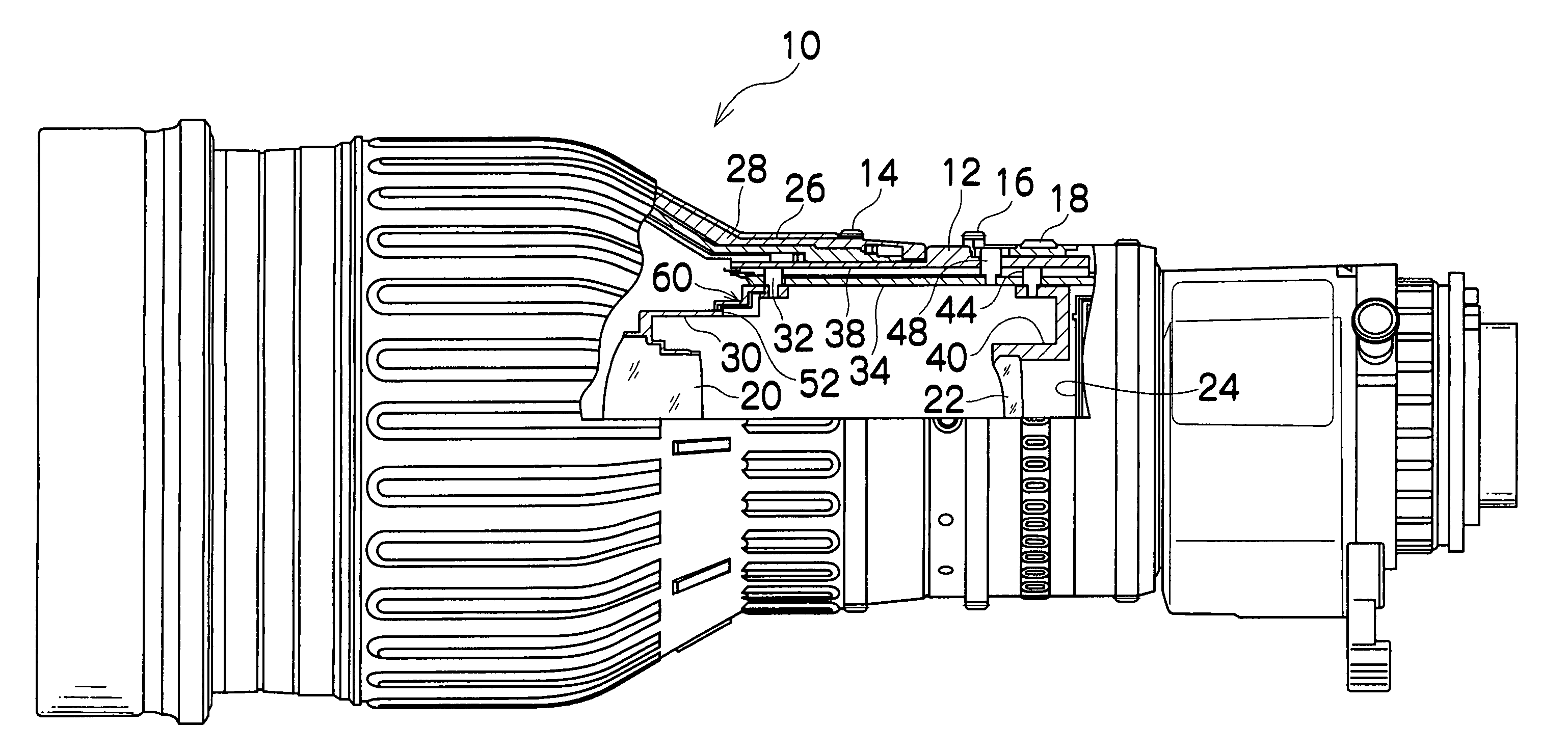
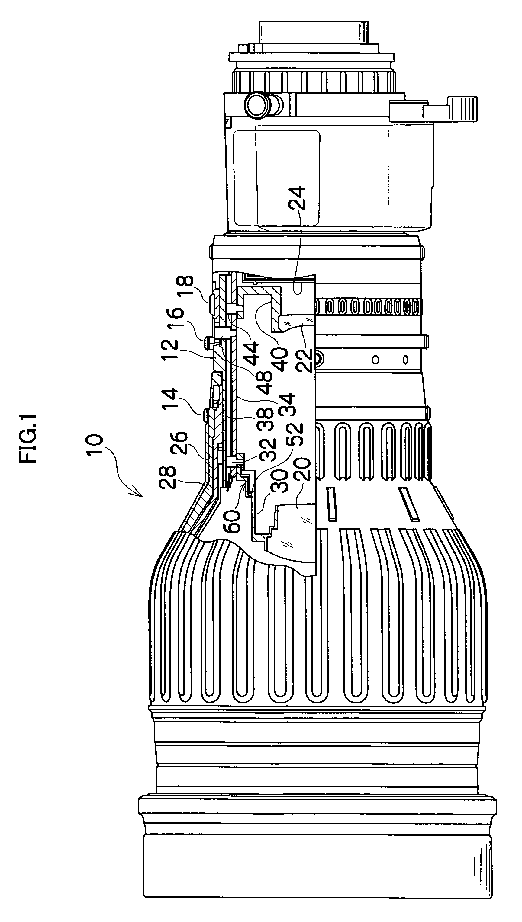
[0025]FIG. 1 is a partially fragmentary sectional view of a zoom lens device 10 for an ENG camera to which the present invention is applied. A focusing ring 14, a zoom ring 15 and an iris ring 18 are rotatably provided on a fixed lens barrel 12 of the zoom lens device 10. In the fixed lens barrel 12 are provided a focusing lens group (not shown), a variable-power lens group (first movable lens) 20, a focus correcting lens group (second movable lens) 22, an iris 24 and a relay lens (not shown) in this order from the left hand side of FIG. 1.

[0026]The focusing lens group is supported on a focusing barrel 26 formed integrally with the focusing ring 14. The focusing barrel 26 is supported by a straight-travel mechanism such as a helicoid screw mechanism or a cam mechanism on a lens barrel 28 fixed on the fixed lens barrel ...


PUM


Abstract

A lens device in which a first movable lens holding frame and a second movable lens holding frame are moved along an optical axis by rotating a cam cylinder rotatably provided on a lens barrel, an escape channel for escapement of a portion of the second movable lens holding frame being formed in the first movable lens holding frame, the lens device comprising:a light shielding member moved along the optical axis by the rotation of the cam cylinder, the light shielding member being moved to a position at which the light shielding member closes the escape channel of the first movable lens holding frame.

Description

BACKGROUND OF THE INVENTION[0001]1. Field of the Invention[0002]The present invention relates to a lens device and, more particularly, to a lens device in which a first movable lens holding frame and a second movable lens holding frame are moved forward or rearward along an optical axis by rotating a cam cylinder to perform zooming.[0003]2. Description of the Related Art[0004]In zoom lens devices for electric news gathering (ENG) cameras, a type of zoom lens device is dominant in which zooming is performed by two movable lens group: a first movable lens group functioning as a variable-power lens group, and a second movable lens functioning as a focus correcting lens group. A cam cylinder is rotatably provided in the lens barrel of such a zoom lens device. In the cam cylinder are formed cam channels engaged with cam rollers projecting from a frame for holding the first movable lens group (hereinafter referred to as “first movable lens holding frame”) and a frame for holding the secon...

Claims


Application Information

Patent Timeline
Patent Type & Authority Patents(United States)
IPC IPC(8): G02B15/14G02B7/02G03B17/00G03B7/099G02B7/04
CPCG02B7/10
Inventor YAMAMOTO, SHIGERU
Owner FUJI PHOTO OPTICAL CO LTD
Why Eureka
Try Eureka