
System and method for configuration discovery in an optical network

a technology of optical network and configuration discovery, applied in the field of information discovery, can solve problems such as network deviating from the planned configuration,

Active Publication Date: 2014-04-01
CIENA
View PDF10 Cites 10 Cited by
  • Summary
  • Abstract
  • Description
  • Claims
  • Application Information

AI Technical Summary

Problems solved by technology

Moreover, in some optical networks there are parameters, such as span loss, that must be within a design range in order for the network to function properly.
Configuration errors may occur during the set-up, repair, upgrading, or operation of an optical network.
In some cases, the network may deviate from the planned configuration because of human error during initial set-up, repair, or upgrading.
For example, a technician may accidentally hook up the wrong optical fibers to the node ports, select the wrong node type, or select an incorrect node setting or node component for a node.
Additionally, the network may deviate from the planned configuration if one or more network parameters or node parameters degrades over time.
For example, effective span losses may increase over time, resulting in the actual network span loss being different than the planned network span loss.
The frequency at which configuration errors occur tends to increase with the number of network nodes and the complexity of the node design.
Thus, while the discovery of configuration errors is important for all optical networks it is becoming an increasingly important issue in complex optical networks, particularly those in which each node must be selected to be compatible with the other nodes of the network.

Method used


Image

  • System and method for configuration discovery in an optical network
  • System and method for configuration discovery in an optical network
  • System and method for configuration discovery in an optical network

Examples


Embodiment Construction

[0021]The present invention generally comprises a system and method for discovering configuration information associated with an optical network. The discovered configuration information may be used to identify configuration errors in the optical network.

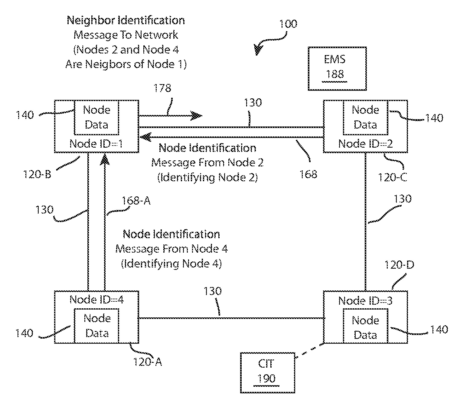
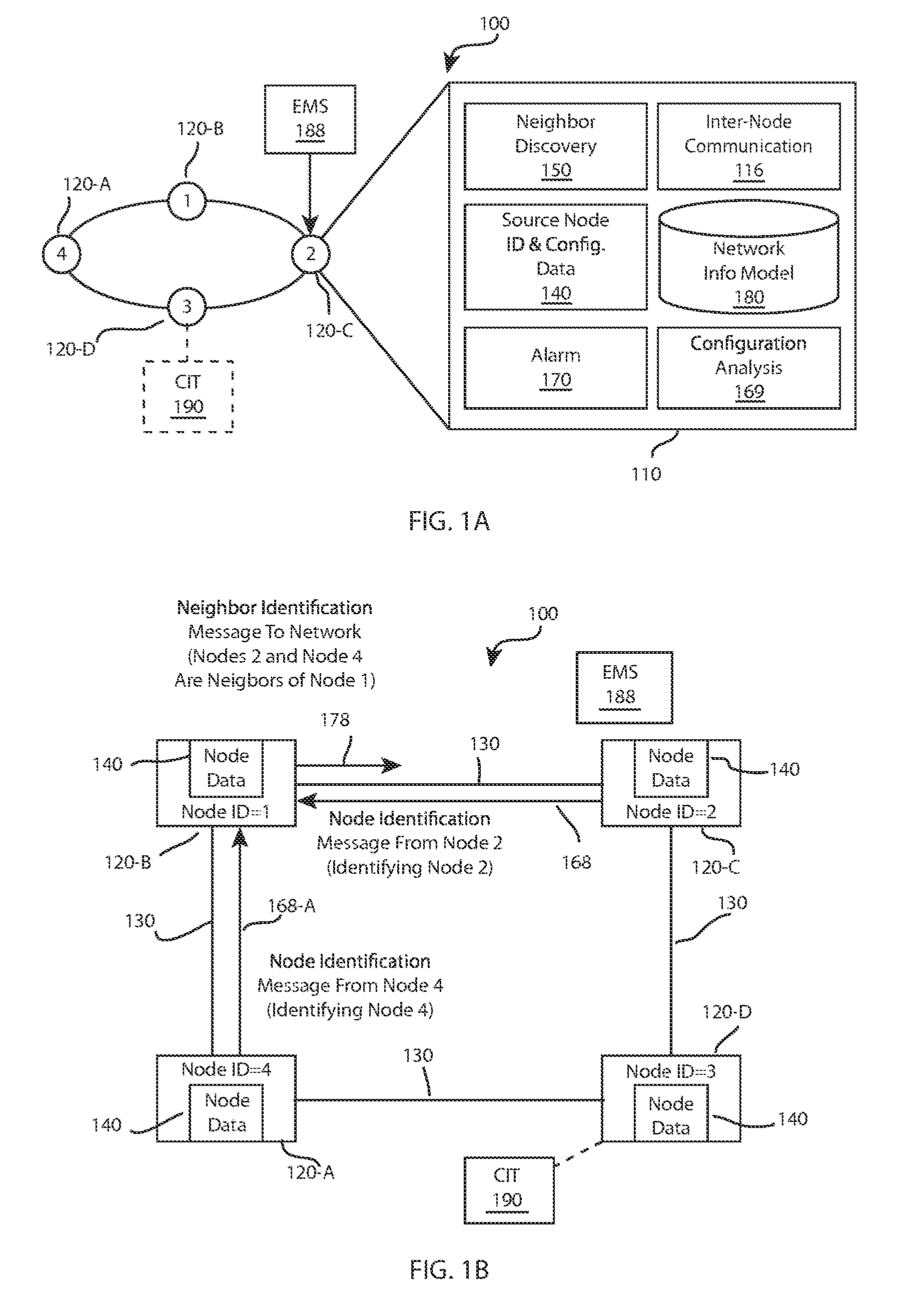
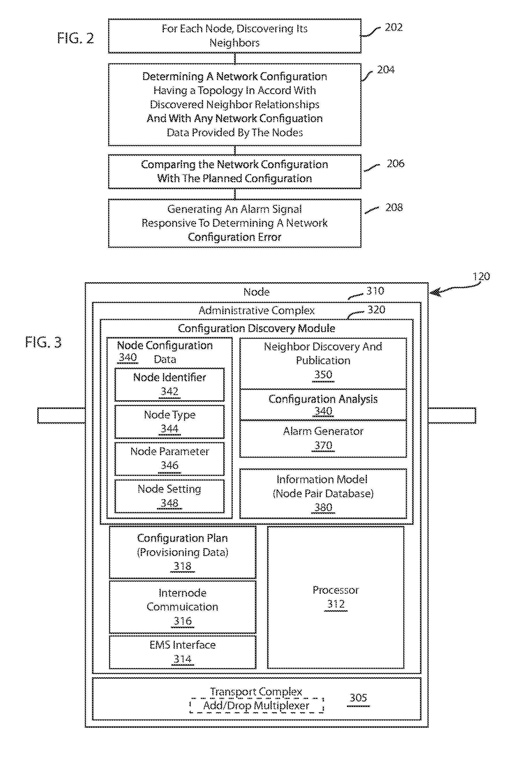
[0022]FIG. 1A is a high-level block diagram of an optical network 100 that includes a plurality of optical nodes 120. In one embodiment the optical network is a wavelength division multiplexed (WDM) optical network, such as a dense wavelength division multiplexed (DWDM) network. However, more generally, optical network 100 does not have to be a WDM network but may comprise a variety of optical network types, such as a time division multiplexed (TDM) network. Each individual optical node 120 is coupled to adjacent (neighboring) nodes by an optical span 130 comprising at least one optical fiber. Each node has node interfaces with one or more ports (not shown in FIG. 1 A) for each span to be coupled to the node. While FIG. 1A shows a r...


PUM


Abstract

A system and method for discovering configuration errors in an optical network is disclosed. The neighbors of each node are discovered. An information model of the optical network is formed, which may be used to determine configuration errors. In one embodiment, each node exchanges node identification messages with neighboring nodes to discover its neighbors, publishes the node neighbor information to the optical network, and forms its own information model from the node neighbor information published by the nodes.

Description

[0001]“This application is a continuation of U.S. patent application Ser. No. 10 / 071,951 filed Feb. 6, 2002. Applicant claims the benefit of the filing date this earlier filed application.”BACKGROUND OF THE INVENTION[0002]1. Field of the Invention[0003]The present invention relates generally to discovering information indicative of the configuration of an optical network. More particularly, the present invention is directed to discovering configuration errors in optical networks.[0004]2. Description of Background Art[0005]An optical network is typically configured for a particular application by provisioning the optical nodes to provide desired services between selected optical nodes. For example, in a wavelength division multiplexed (WDM) optical network, such as a dense wavelength divisions multiplexed (DWDM) network, the nodes may be provisioned to add, drop, or pass-through desired wavelength channels. Proper configuration of an optical network can also include selecting compati...

Claims


Application Information

Patent Timeline
Patent Type & Authority Patents(United States)
IPC IPC(8): H04B10/00
CPCH04J14/0267H04J14/0275H04J14/0272H04B10/0773H04J14/0227H04J14/0283H04J14/0246H04J14/025H04J14/0284
Inventor MUPPIDI, SRINIVASA SESHA SOMA SEKHARRAMANAN, GOPINATH
Owner CIENA
Learn More