Feedback light tuning device and optical communication system and method using the same

a technology of light tuning and optical communication system, which is applied in the field of feedback light tuning technique, can solve the problems of reducing power and bandwidth, sacrificing output power or bandwidth, and unable to meet the requirements of high-precision gyroscope light sources, etc., and achieves the effect of stabilizing the mean wavelength dri

Active Publication Date: 2014-04-01
NAT TAIWAN UNIV
View PDF5 Cites 3 Cited by
  • Summary
  • Abstract
  • Description
  • Claims
  • Application Information

AI Technical Summary

Benefits of technology

[0010]To effectively diminish mean wavelength drift of the SFS in harsh environments, the invention discloses a novel and useful feedback light tuning device along with the optical communication system and method using the same that can rapidly stabilize the mean wavelength drift caused by the harsh environments.
[0011]The disclosed feedback light tuning device is used in an optical communication device with a SFS and a light source output terminal. It includes: a wide band splitter, a mean wavelength detection module, and a feedback light control module. The wide band splitter is connected with the SFS in the optical communication device via an optical fiber, thereby receiving a first-direction emission emitted by the SFS. After splitting the first-direction emission into a first beam and a second beam, the wide band splitter outputs the first beam to the light source output terminal and feeds back the second beam. The mean wavelength detection module is connected with the wide band splitter via an optical fiber for receiving the second beam fed back from the wide band splitter, thereby computing the mean wavelength drift. The feedback light control module is electrically connected with the mean wavelength detection module and connected to the SFS via an optical fiber for receiving the second-direction emission emitted by the SFS in the opposite direction of the first emission. The feedback light control module according to an electrical signal based on the mean wavelength drift from the mean wavelength detection module generates and controls feedback light which propagates into the SFS to cause gain competition. Such gain competition can tune and correct the mean wavelength of the first-direction emission.
[0014]As described above, the SFS is connected with the feedback light control module. When the feedback light tuning technique is activated, the mean wavelength drift caused by harsh environments can usually be reduced to 1%, preferably at least 0.1%, and most preferably at least 0.01%. The working range is the temperature variation or radiation dose causing the mean wavelength drift of 30 nm or 19400 ppm when the feedback light tuning technique is not activated. In comparison with the prior art in which a filter is employed to attain stability in the mean wavelength of the SFS, the proposed feedback light tuning technique can greatly increase both bandwidth and power. Therefore, the light source efficiency is superior to the prior art. The invention is very suitable for aerospace technology and nuclear facilities, i.e., for environments with large temperature variation or irradiation. The applications include communications, sensings, and navigations.
[0016]Briefly, the invention discloses an optical fiber assembly operating in harsh environments. In particular, it stabilizes the mean wavelength drift of a RE-doped SFS. The stability of the mean wavelength thanks to the function of the feedback light control module.

Problems solved by technology

However, this method also reduces the power and bandwidth (e.g., ≦10 nm), unable to satisfy the requirements on the light source for high-precision gyroscopes.
Moreover, using the filter to achieve the stability of the mean wavelength of the SFS in the prior art has to sacrifice the output power or bandwidth to some extent.
In a radiation environment, the SFS cannot meet the requirements of the light source for high-precision gyroscopes; i.e., high output power, wide bandwidth (30 nm) and stability in the mean wavelength at the same time.
Lately, optical communication systems have demand to be applied in harsh environments, such as those with a large temperature variation or a lot of radiation.

Method used


Image

  • Feedback light tuning device and optical communication system and method using the same
  • Feedback light tuning device and optical communication system and method using the same
  • Feedback light tuning device and optical communication system and method using the same

Examples


Embodiment Construction

[0024]The present invention will be apparent from the following detailed description, which proceeds with reference to the accompanying drawings, wherein the same references relate to the same elements.

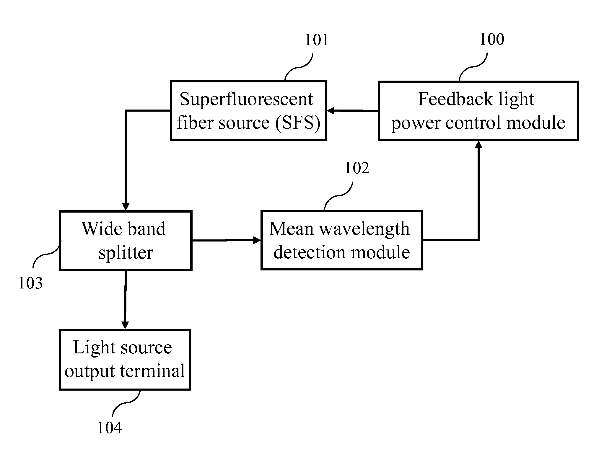
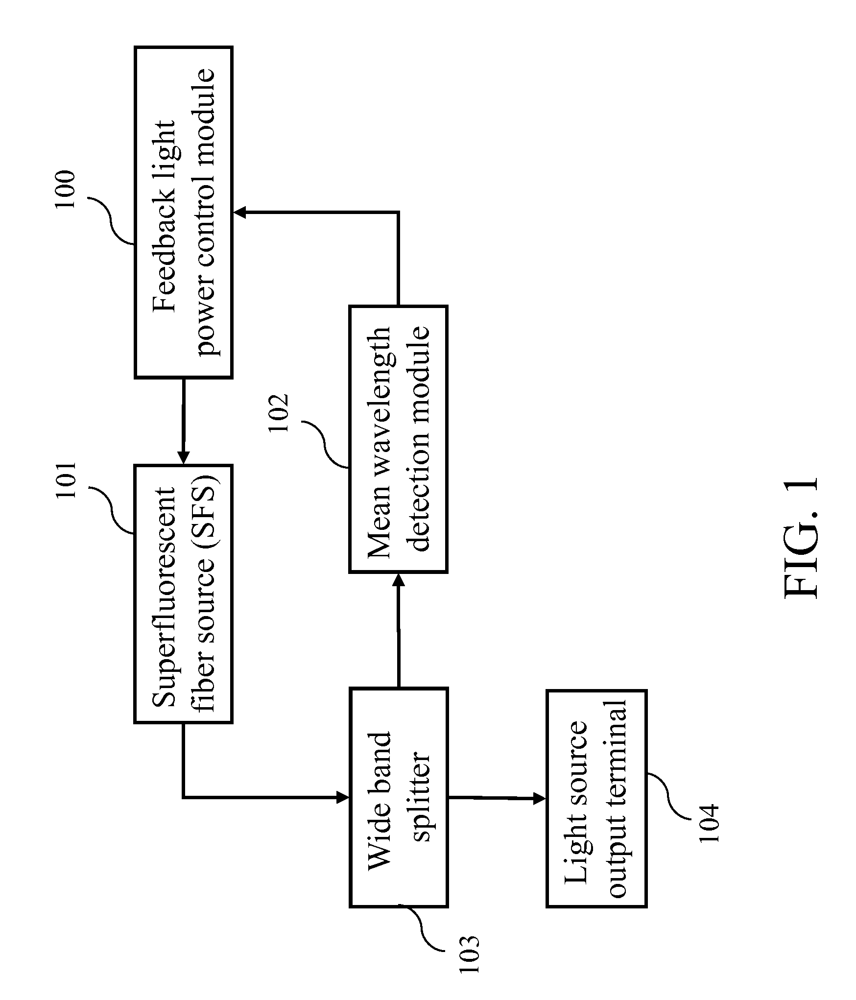
[0025]Please refer to FIG. 1, which is a block diagram of the disclosed feedback light tuning device. The device is used in an optical communication device with an SFS 101 and a light source output terminal 104. The feedback light tuning device includes: a wide band splitter 103, a mean wavelength detection module 102, and a feedback light control module 100. The wide band splitter 103 is connected via an optical fiber with the SFS 101 for receiving first-direction emission emitted by the SFS 101. After the first-direction emission is split into a first beam and a second beam, the first beam is output to the light source output terminal 104 and the second beam is fed back to the mean wavelength detection module 102. In practice, the SFS 101 uses a light-emitting element (e.g., laser d...


PUM


Abstract

A feedback light tuning device and the optical communication system and method using the same are provided. By tuning the feedback light, the mechanism can completely correct the mean-wavelength drift up to 30 nm or 19400 ppm. The mechanism can be applied to various harsh environments which cause the mean-wavelength drift, so as to achieve a required stable mean-wavelength for the light source and to increase the acceptable range of radiation dose.

Description

CROSS-REFERENCE TO RELATED APPLICATION[0001]This application claim priority to a TAIWAN patent application numbered 101102516 filed on Jan. 20, 2012 (TAIWAN time), which is hereby incorporated by reference in its integrity.BACKGROUND OF THE RELATED ART[0002]1. Technical Field[0003]The invention relates to a feedback light tuning technique and, in particular, to a technique that applies to superfluorescent fiber source (SFS) and reduces mean wavelength drifts caused by environment changes using feedback light tuning.[0004]2. Related Art[0005]In both engineering and scientific domains, optical communication systems are important tools because of their high sensitivity and stability for sensing applications. In particular, they are immune to electromagnetic interference (EMI).[0006]The light source is an essential element in an optical communication system with demands of high output power, broad bandwidth, and stable mean wavelength. Since SFSs doped with rare earth (RE) ions have bee...

Claims


Application Information

Patent Timeline
Patent Type & Authority Patents(United States)
IPC IPC(8): H04B10/572
CPCH04J14/02H04B10/572
Inventor PENG, TZ SHIUANWANG, LON
Owner NAT TAIWAN UNIV
Why Eureka
Try Eureka