Fall away arrow rest system

a rest system and arrow rest technology, applied in the field of falling away arrow rest system, can solve the problems of changing the desired trajectory and flight path, arrow rests have inherent deficiencies, adverse effects, etc., and achieve the effect of reducing or substantially eliminating noise and reducing nois

Active Publication Date: 2014-04-22
BLACK GOLD ARCHERY LLC
View PDF10 Cites 20 Cited by
  • Summary
  • Abstract
  • Description
  • Claims
  • Application Information

AI Technical Summary

Benefits of technology

[0007]The present invention also involves the provision of a launcher adapted to be coupled with an arrow rest. The launcher is designed to reduce or substantially eliminate the noise developed when an arrow shaft moves or rattles within the launcher. The launcher may include a base and a pair of arms extending from the base forming a channel therebetween. The launcher is constructed of at least two different materials—a first material having a first hardness and second material having a second hardness that is less than the first hardness. The launcher may be formed through an overmolding process. In such a case, at least a portion of the base and arms may be formed of a molded plastic material and may be at least partially overlaid and / or embedded with a rubber material. In one embodiment, the inside surfaces of the arms and the area where the arms meet the base are overlaid with a rubber material in order to reduce the noise developed as an arrow shaft moves or rattles within the channel.

Problems solved by technology

One common problem with arrow rests is that the fletching of the arrow, which is necessary for stable arrow flight, may contact the arrow rest when the arrow is fired, thereby changing the desired trajectory and flight path of the arrow.
However, such arrow rests have inherent deficiencies.
This can have an adversely impact by altering the desired trajectory and flight path of the arrow.
Another common problem with arrow rests lies in the design of the support element or launcher in which the arrow is held.
The arrow shaft, which may be formed from a metallic, plastic, wood, carbon fiber or fiberglass material, creates noise as it moves within the launcher.
This noise creates a certain disadvantage to users hunting game, and is especially problematic when the user has sighted game and draws the arrow back to be fired, as the noise can alert the animal of the hunter's presence.
However, these materials undergo wear and can be nuisance to keep adhesively attached to the launchers, especially when hunting in the elements of the outdoors.

Method used


Image

  • Fall away arrow rest system
  • Fall away arrow rest system
  • Fall away arrow rest system

Examples


Embodiment Construction

[0019]The invention will now be described with reference to the drawing figures, in which like reference numerals refer to like parts throughout. For purposes of clarity in illustrating the characteristics of the present invention, proportional relationships of the elements have not necessarily been maintained in the drawing figures.

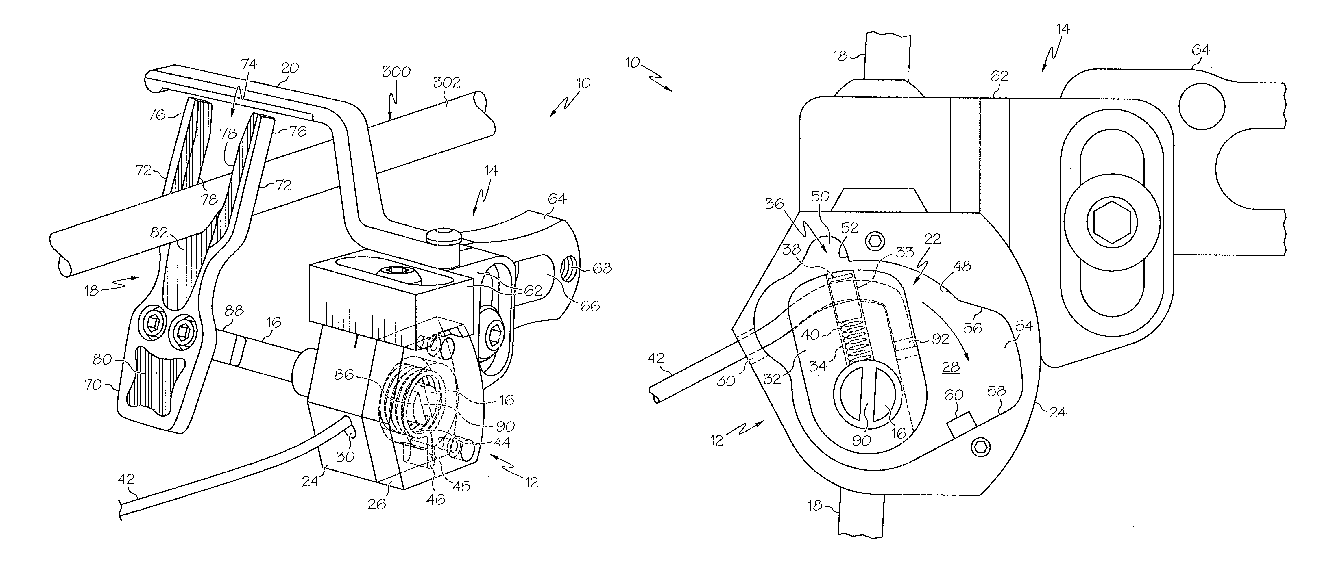
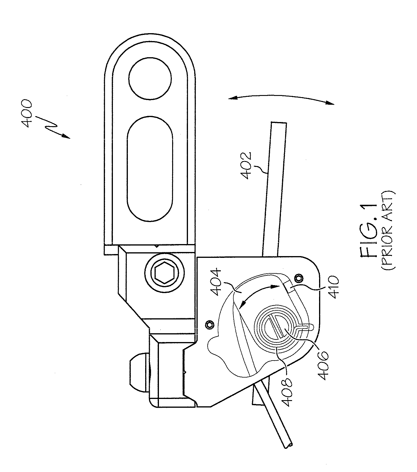
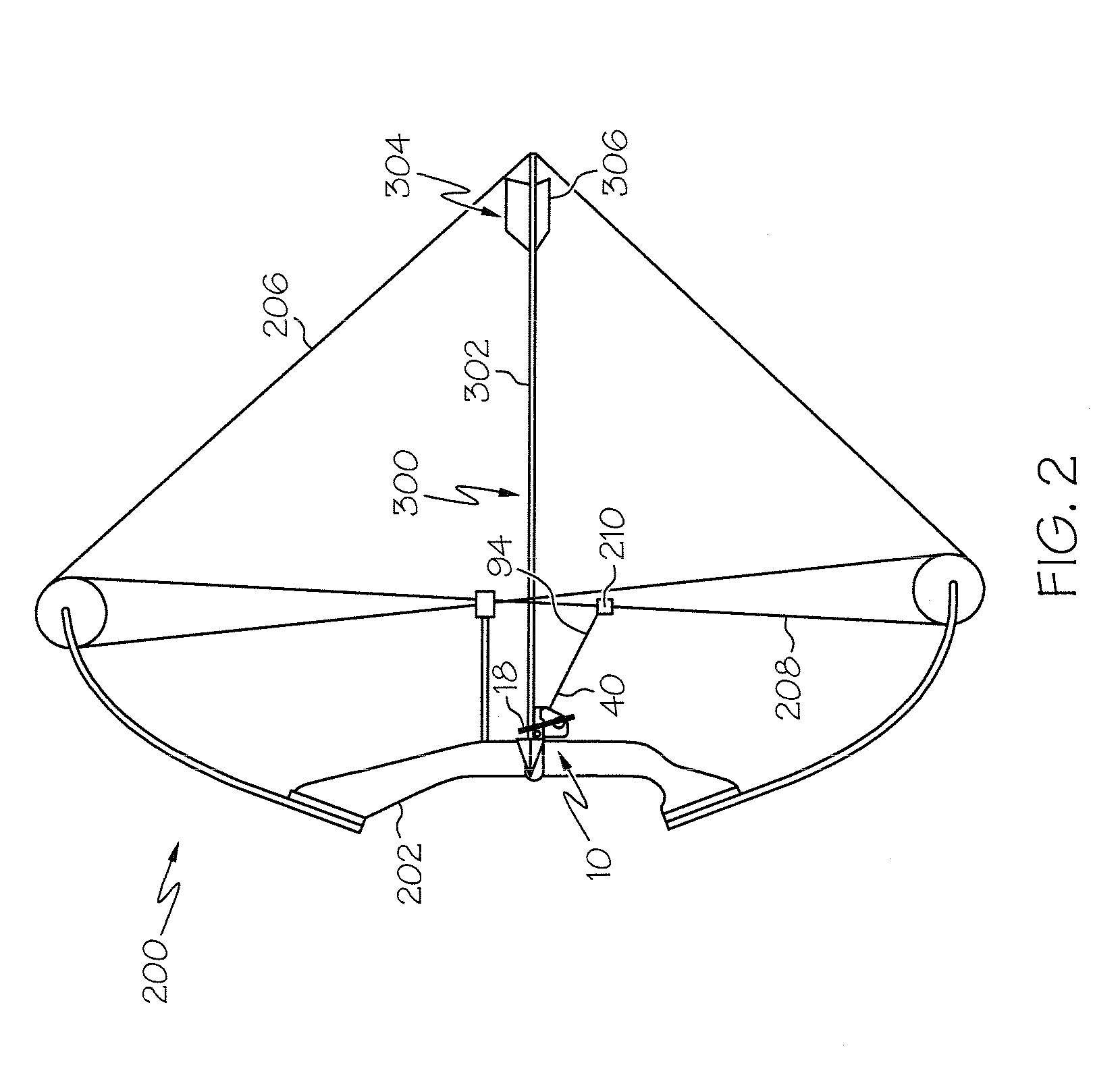
[0020]The present invention is directed generally to an improved fall away arrow rest system 10. The arrow rest 10 is designed to overcome deficiencies of known arrow rests, including the one indicated by reference 400 in FIG. 1. As illustrated in FIG. 2, the arrow rest 10 is adapted for use with a bow, such as a compound bow 200, having a frame 202 and a bow string 206. While FIG. 2 shows the bow 200 being in a vertical orientation where arrow 300 is aligned in a longitudinal direction on the launcher 18, arrow 300 may obviously be fired from any number of orientations depending upon the desired flight path.

[0021]FIGS. 3A and 3B present a more detailed ...


PUM


Abstract

The present invention is directed to a fall away arrow rest system for use with a bow. The arrow rest system includes a launcher that is adapted to support a shaft of an arrow prior to the firing of the arrow. Upon the firing of the arrow, the launcher rotates from an upright position to a lowered position in order to move out of the way by the time the tail region of the arrow passes by the launcher. The arrow rest includes a activator body with a locking component to releasably secure the launcher in a lowered position in order to substantially eliminate any bounce back of the launcher and possibility that it may contact the arrow after the arrow is fired.

Description

CROSS-REFERENCE TO RELATED APPLICATIONS[0001]None.BACKGROUND OF THE INVENTION[0002]Arrow rests for compound bows provide a user with a steady surface on which the user can place the shaft of an arrow as the user prepares to aim and fire the arrow at a target. More specifically, arrow rests allow the user to make aiming adjustments based on the surrounding environmental conditions (e.g., wind speed and direction) while reducing the tendency of dropping of the arrow.[0003]One common problem with arrow rests is that the fletching of the arrow, which is necessary for stable arrow flight, may contact the arrow rest when the arrow is fired, thereby changing the desired trajectory and flight path of the arrow. So-called “drop away” arrow rests have been developed to reduce the tendency of the fletching contacting the arrow rest when the arrow is fired. Drop away arrow rests, such as the one described and shown in U.S. Pat. No. 7,409,950, normally include a support element or launcher desig...

Claims


Application Information

Patent Timeline
Patent Type & Authority Patents(United States)
IPC IPC(8): F41B5/22
CPCF41B5/143F41B5/1438
Inventor ELLIG, MICHAEL, J.
Owner BLACK GOLD ARCHERY LLC
Why Eureka
Try Eureka