Multilayer infrared reflecting film with high and smooth transmission in visible wavelength region and laminate articles made therefrom

a multi-layer, infrared technology, applied in the direction of optical elements, lighting and heating apparatuses, instruments, etc., can solve the problems of reflection spectrum, unwanted colors created by multi-layer polymeric ir reflecting film designs, unwanted variation or modulation in the visible portion of the transmission spectrum, etc., to achieve high visible light transmission and enhance performance

Inactive Publication Date: 2007-06-26
3M INNOVATIVE PROPERTIES CO
View PDF18 Cites 64 Cited by
  • Summary
  • Abstract
  • Description
  • Claims
  • Application Information

AI Technical Summary

Benefits of technology

[0013]The multilayer IR reflecting film designs described above have very high visible light transmission, and are useful as IR mirrors or IR polarizers in automotive glazing laminates. When used in a windshield laminate construction, these IR mirrors and polarizers have low reflection in the ...

Problems solved by technology

The unwanted colors created by the multilayer polymeric IR reflecting film designs described above result from noise (i.e., un...

Method used


Image

  • Multilayer infrared reflecting film with high and smooth transmission in visible wavelength region and laminate articles made therefrom
  • Multilayer infrared reflecting film with high and smooth transmission in visible wavelength region and laminate articles made therefrom
  • Multilayer infrared reflecting film with high and smooth transmission in visible wavelength region and laminate articles made therefrom

Examples


example 1

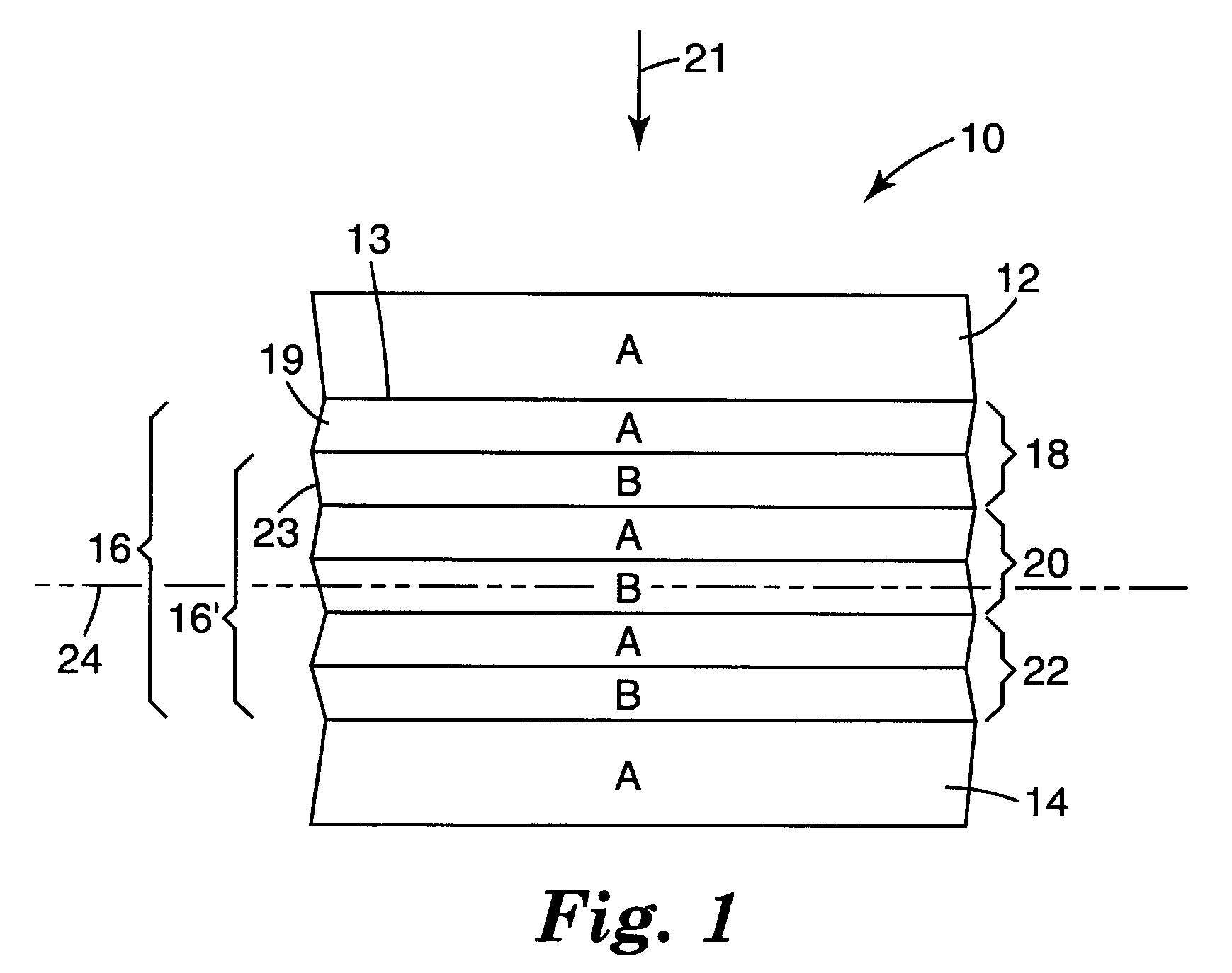
[0119]An IR reflective multilayer film with a 711 construction was simulated via computer model so that it included unit cells with layers having optical thickness ratios of 7A1B1A7B1A1B. Skin and protective boundary layers were applied that had the same index of refraction as one of the optical layers.

[0120]In Example 1a, the film had the following layer construction:

[0121](skin / PBL_A) 7A1B1A7B1A1B . . . 7A1B1A7B1A1B (skin / PBL13 A)

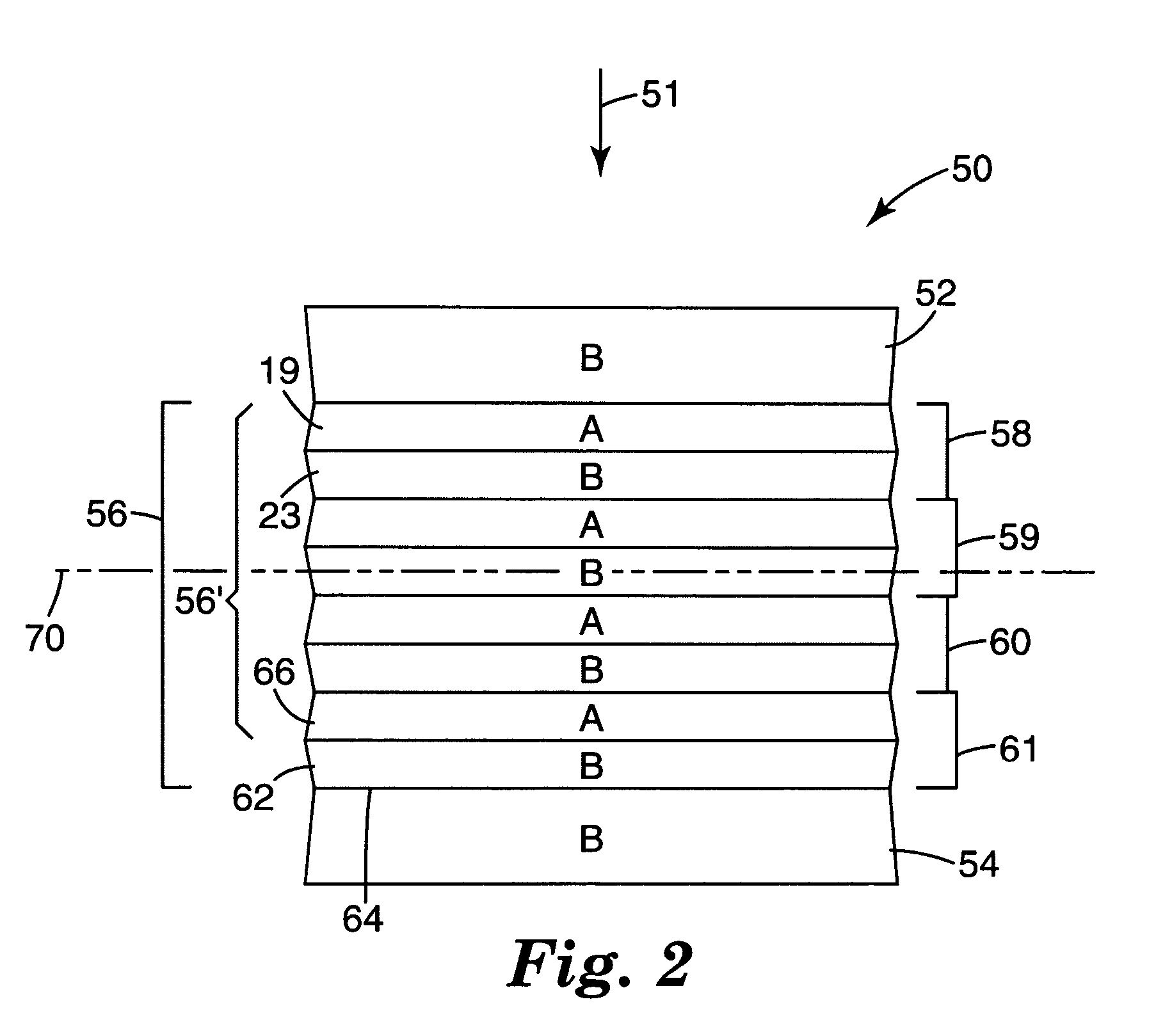
[0122]In Example 1b, the film had the following layer construction:

[0123](skin / PBL_A) 7B1A1B7A1B1A . . . 7B1A1B7A1B1A (skin / PBL_A)

[0124]In both Examples 1a and 1b, the outer most A layer in the optical packet merges with skin / PBL, so the total number of layers in the effective optical packet is 6n−1, where n is the number of unit cells in the packet before merging. For these examples n was set to 32. Also, both Examples 1a and 1b used a simple linear layer thickness gradient of 1.27 (the ratio of the optical thickness of the thickest to the thin...

example 2

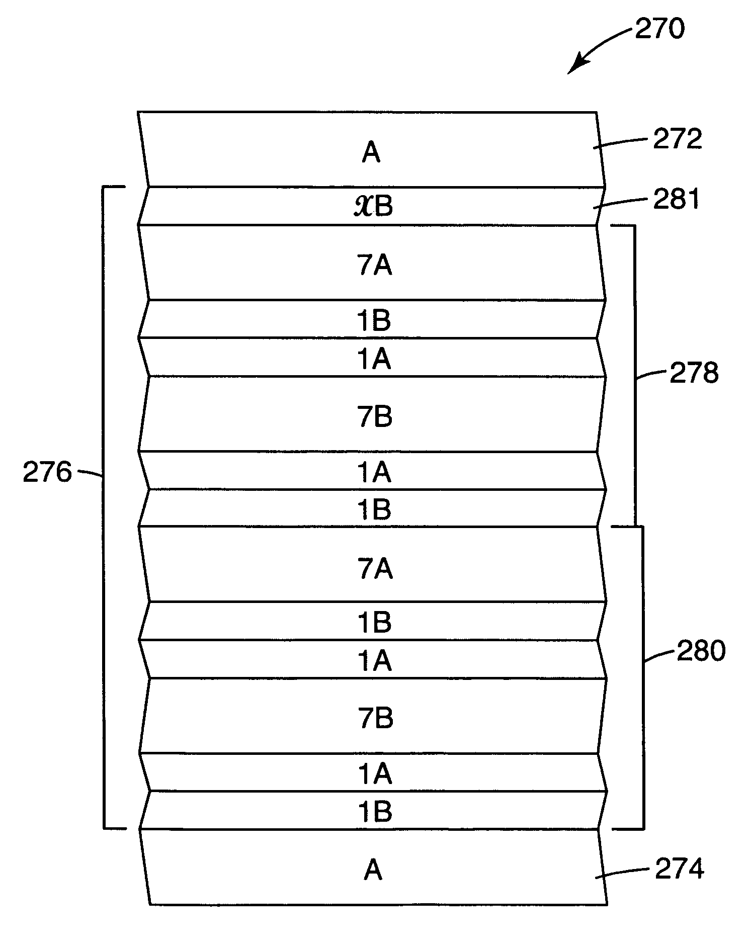
[0133]IR reflective multilayer IR films were modeled by adding an additional layer B with (relative) thickness x between the outer most A layer and skin / PBL of the construction in Example 1.

[0134]In Example 2a, the film had the following construction:[0135](skin / PBL_A) (xB) 7A1B1A7B1A1B . . . 7A1B1A7B1A1B (skin / PBL_A)

[0136]Example 2b, the film had the following construction:[0137](skin / PBL_A) 7B1A1B7A1B1A . . . 7B1A1B7A1B1A (xB) (skin / PBL13 A)

[0138]In either case, the total number of layers in the effective optical packet is 6n+1, where n is the number of unit cells in the packet without the extra layer. The film construction in Example 2a does not have symmetry regardless of the thickness of the xB layer. The film construction in Example 2b achieves symmetry only when x=7.

[0139]The spectra in FIG. 15 were obtained for three simulated films according to Example 2a with x=1, 7, and 20 respectively, each such film having three optical packets with 32 unit cells in each packe...

example 3

[0145]In these simulated constructions, the skin / PBL had an index of refraction different from the index of refraction of either of the materials in the optical stack.

[0146]Three cases were considered:

[0147]Example 3a: skin / PBL index>the index of the high index optical material

[0148]Example 3b: the index of the low index optical material

[0149]Example 3c: skin / PBL index

[0150]The simulated spectra were obtained for each example using a 711 optical stack construction with a layer arrangement of approximately 7A1B1A7B1A1B . . . 7A1B1A7B1A1B in each of the three packets. The film was constructed as: skin / PBL (packet 1) PBL (packet 2) PBL (packet 3) skin / PBL with each packet having 32 unit cells. The high index optical material was low melt point PEN with index of refraction 1.73 (along both in-plane directions), the low index optical material was PMMA with index 1.49 (along all direction...


PUM

PropertyMeasurementUnit
Fractionaaaaaaaaaa
Wavelengthaaaaaaaaaa

Abstract

A multilayer film article is disclosed. The film includes an infrared light reflecting multilayer film having alternating layers of a first polymer type and a second polymer type and an infrared light absorbing or reflecting layer adjacent the multilayer film. The film includes a multilayer stack composed of alternating optical layers of first and second diverse polymers A, B. The optical layers when counted from one end of a first effective optical packet form a plurality of unit cells each having six optical layers arranged in relative optical thicknesses in a first cyclic permutation of 7A1B1A7B1A1B. At normal incidence the first effective optical packet provides a reflection band at infrared wavelengths and substantially transmits light at visible wavelengths.

Description

CROSS REFERENCE TO RELATED APPLICATIONS[0001]This application is a continuation of application Ser. No. 10 / 613,500, filed Jul. 3, 2003, now U.S. Pat. No. 6,927,900, which is a continuation of PCT International Application No. PCT / US02 / 01103, filed Jan. 15, 2002, which claims priority to U.S. Provisional Application Ser. No. 60 / 261,942, filed Jan. 15, 2001, now expired.TECHNICAL FIELD[0002]This invention relates to dielectric multilayer reflecting films (including coatings applied to substrates) and laminate articles made therefrom.BACKGROUND[0003]A conventional automotive safety glazing is formed from a laminate made of two rigid layers, typically glass, and an anti-lacerative mechanical energy absorbing interlayer of plasticized polyvinyl butyral (PVB). The glazing is prepared by placing the PVB layer between glass sheets, eliminating air from the engaging surfaces, and then subjecting the assembly to elevated temperature and pressure in an autoclave to fusion bond the PVB and glas...

Claims


Application Information

Patent Timeline
IPC IPC(8): G02B5/08G02B1/10B32B7/02B32B17/10G02B1/11G02B5/28
CPCB32B17/10B32B17/10761B32B17/10807B32B17/10862G02B5/0841G02B5/282B32B2367/00B32B17/10005G02B5/28
Inventor LIU, YAOQI J.SIEVERS, JERRY A.RUFF, ANDREW T.
Owner 3M INNOVATIVE PROPERTIES CO
Why Eureka
Try Eureka