Rack mount device

a technology for mounting devices and racks, which is applied in the direction of dismountable cabinets, curtain suspension devices, furniture parts, etc., can solve the problems of loosing the attachment screws, affecting the stability of the rack,

Active Publication Date: 2014-04-22
NEC ASIA PACIFIC PTE LTD
View PDF55 Cites 21 Cited by
  • Summary
  • Abstract
  • Description
  • Claims
  • Application Information

AI Technical Summary

Benefits of technology

[0019]In order to overcome each of the foregoing issues, it is an exemplary object of the present invention to provide a rack mount device for loading a rack loaded device, which can be easily and surely connected and mounted to a rack and can be detached by easily releasing the connection.
[0021]Further, a connection release mechanism is provided to the kit connecting mechanism, so that the connection of the mount kit and the pole brace members can be released by operating the connection release mechanism. Therefore, the mount kits can be detached by releasing the connection easily.

Problems solved by technology

This requires a lot of efforts and troublesome works.
Further, since both rails are fastened by inserting the attachment screws into the attachment holes of the both rails, the attachment screws may be loosened and the both rails may be contracted due to an oscillation and the like if the fastening force is weak.
As a result, the rack loaded device placed on the top face of the L-type rail falls down, and it may be damaged.
Further, when the parallel pins are inserted completely into the pin attachment holes of the mount rail and the like, it may not be always possible to find the optimum attachment screw holes for keeping that state among the plurality of attachment screw holes of the rail and the like.
Thus, even when the attachment screws are inserted into the attachment screw holes in a condition closest to optimum to be fastened, the entire length of the L-type rail becomes short.
This may impose an adverse effect on the rack loaded device.
This work therefore is difficult, so that the efficiency of exchange work becomes poor.
This is not suitable for online maintenance, and the devices to be employed may become limited.
However, with this tool, the tool main body needs to be fixed to the wall with a bolt.
Therefore, there is a difficulty in its attachment and detachment.
However, this structure needs a devise for being applied to the rack mount device, and it cannot be applied as it is.
Thus, this structure cannot be applied to the rack mount device as it is, and it is necessary to apply a devise to be employed to the mount rack device.

Method used


Image

  • Rack mount device
  • Rack mount device
  • Rack mount device

Examples


Embodiment Construction

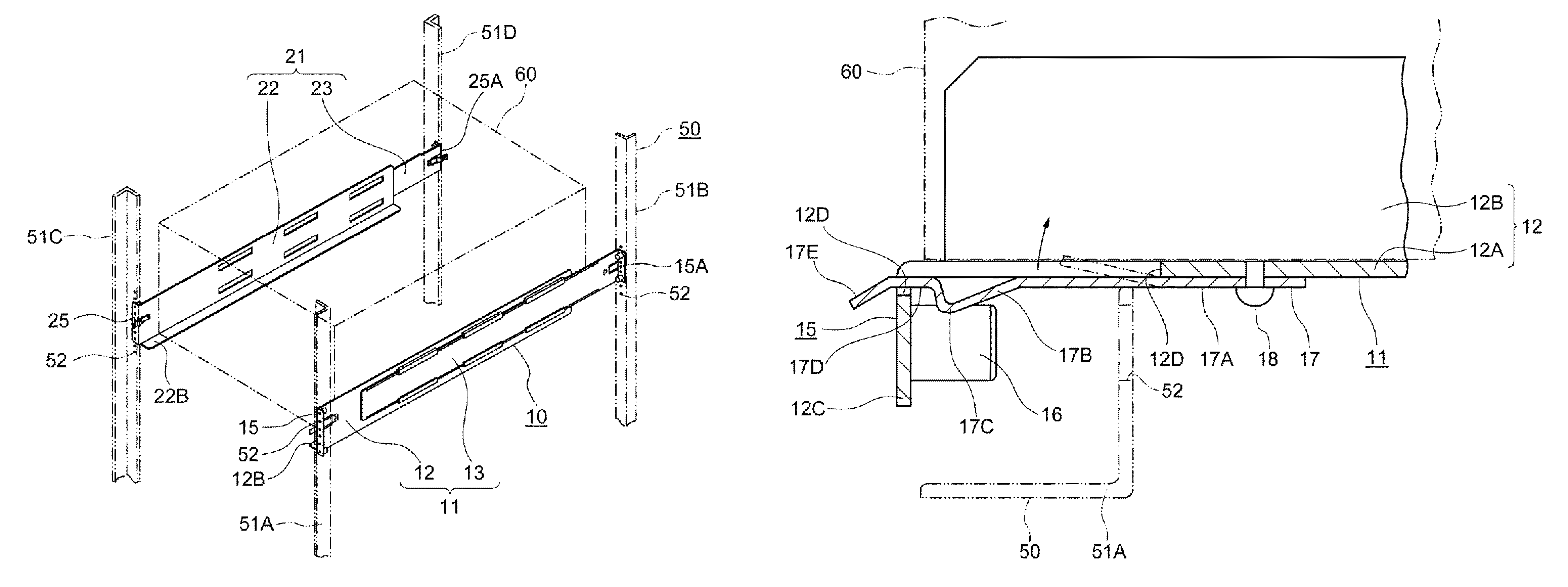
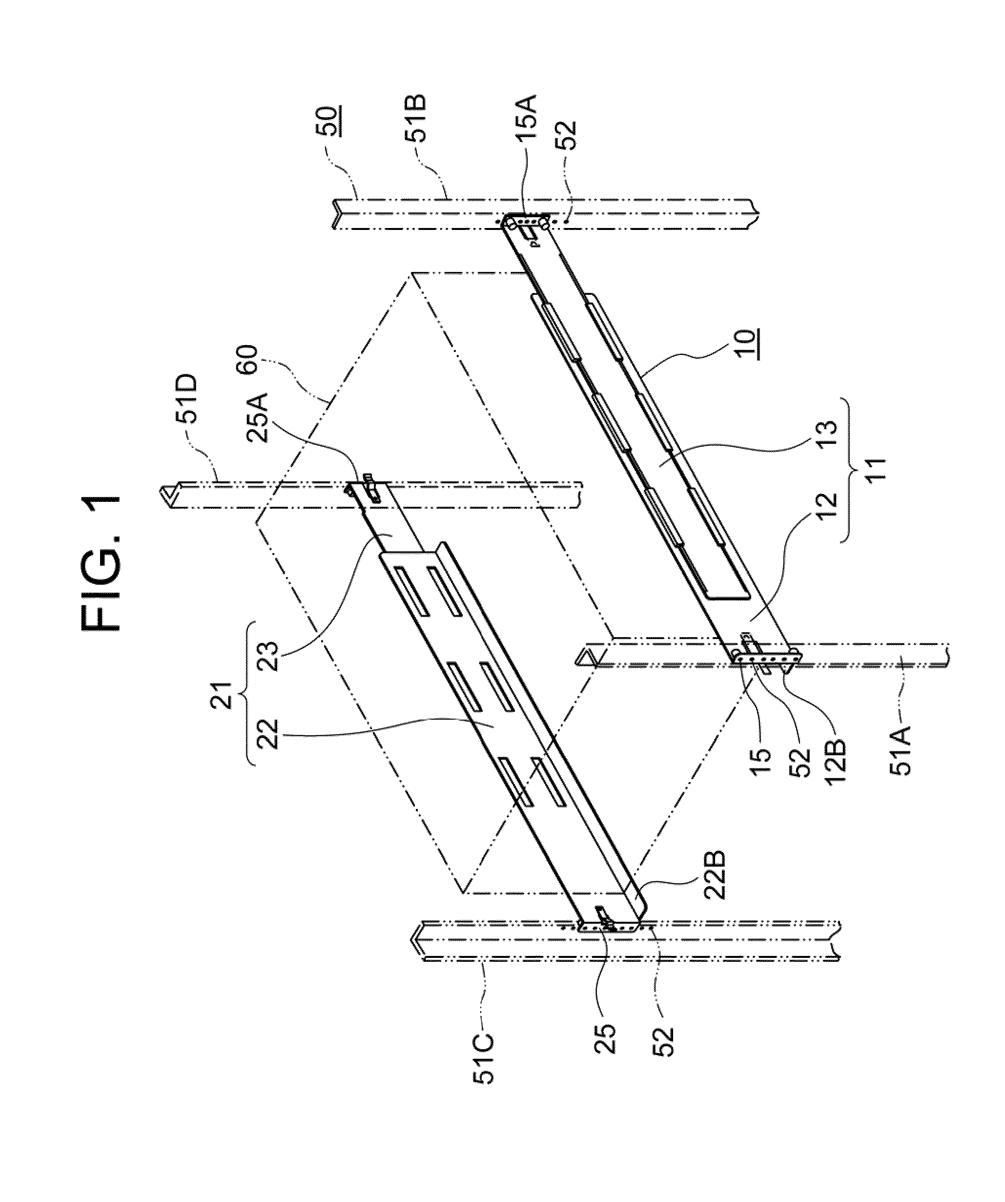
[0041]Hereinafter, a first exemplary embodiment of a rack mount device (simply referred to as a device hereinafter) 10 of the present invention will be described by referring to FIG. 1-FIG. 8.

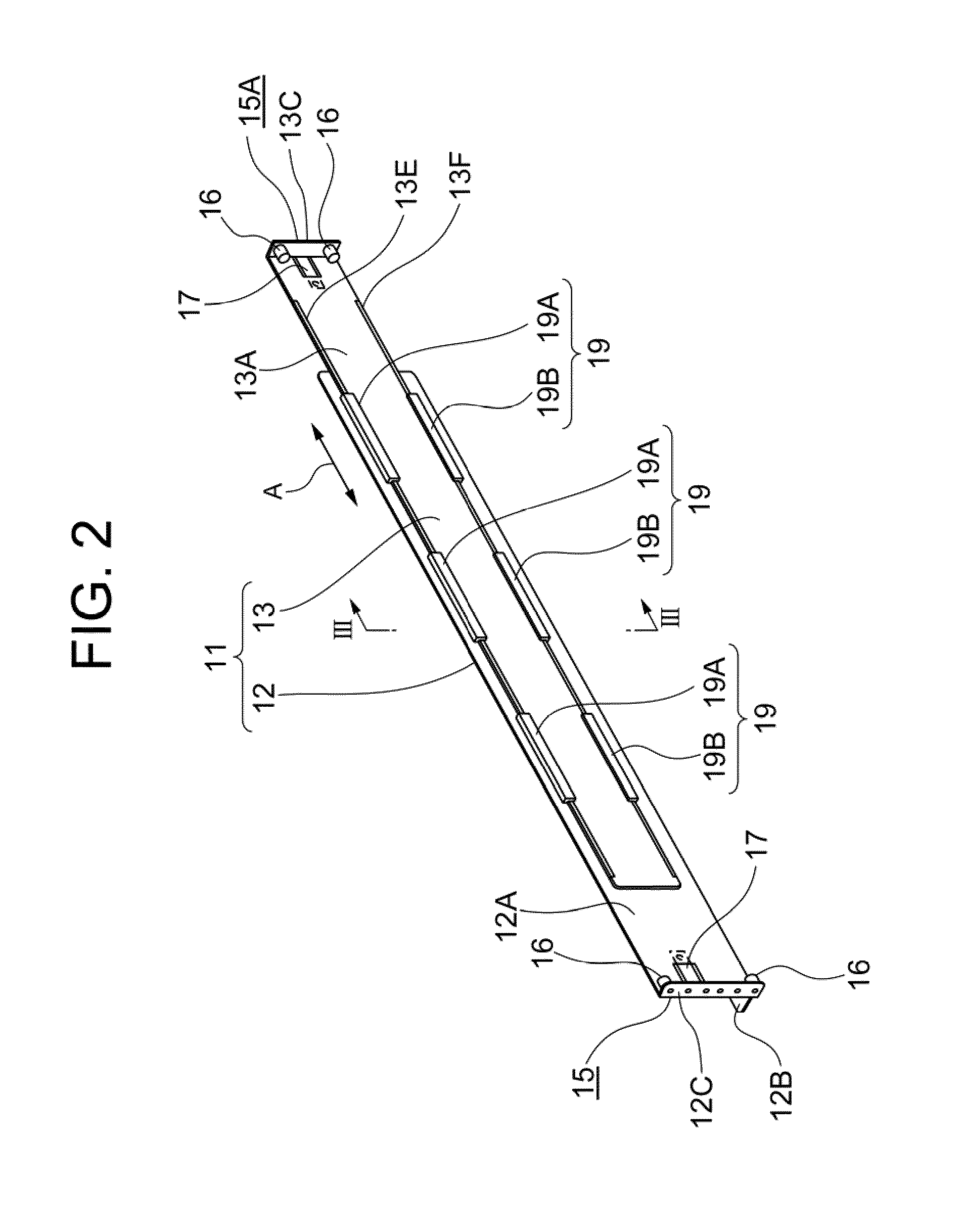
[0042]FIG. 1 shows an overall perspective view of a state where the device 10 is attached to a rack 50. FIG. 2 shows an overall perspective view of a first rack mount kit (simply referred to as a first kit) 11 out of a pair of mount kits which configure the device 10. FIG. 8 shows an overall perspective view of a second rack mount kit (simply referred to as a second kit) 21 out of a pair of mount kits which configure the device 10. The device 10 is provided with a rack loaded device 60 such as an electronic device or the like.

[0043]First, the rack 50 to which the device 10 is attached will be described by referring to FIG. 1.

[0044]The rack 50 includes mount angles 51A, 51B, 51C, and 51D as pole brace members provided at the four corners. Circular positioning holes 52 (also see FIG. 7), for exam...


PUM


Abstract

To be able to connect and mount a rack mount device having a rack loaded device loaded thereon to a rack easily, and to be able to release and detach the rack mount device easily from the outside of the rack. The rack mount device has a pair of mount kits for holding the rack loaded device arranged to oppose to each other, which are detachably connected to four mount angles configuring the rack. Each mount kit is configured with a front mount and a rear mount, which are freely slidable with respect to each other in the longitudinal directions thereof. A kit connecting mechanisms for connecting each mount kit to the mount angles are provided to both ends of the mount kits, respectively. A connection releasing mechanism for releasing the connection between the mount kits and the mount angles is provided to each of the kit connecting mechanisms.

Description

CROSS-REFERENCE TO RELATED APPLICATION[0001]This application is based upon and claims the benefit of priority from Japanese patent application No. 2008-225115, filed on Sep. 2, 2008, the disclosure of which is incorporated herein in its entirety by reference.BACKGROUND OF THE INVENTION[0002]1. Field of the Invention[0003]The present invention relates to a rack mount device and, more specifically, to a rack mount device equipped with a rack loaded device such as an electronic device and the like, which can be easily connected and released to / from a rack.[0004]2. Description of the Related Art[0005]Recently, IT device systems and NW device systems have rack loaded devices suited for designated functions loaded on a plurality of racks in a composite manner to achieve optimization. Further, improvements in the performances and functions of such IT devices and NW devices are prominent, so that frequencies of exchanges, expansions, and the like of the devices have been increased according...

Claims


Application Information

Patent Timeline
Patent Type & Authority Patents(United States)
IPC IPC(8): A47F7/00A47B88/00A47B43/00A47F5/00
CPCH05K7/1421H05K7/1489A47B88/00
Inventor OURA, NORIHIRO
Owner NEC ASIA PACIFIC PTE LTD
Why Eureka
Try Eureka