Relay connector for flexible cables

a flexible cable and connector technology, applied in the direction of electrical apparatus, connection, coupling device connection, etc., can solve the problems of difficult to increase the number of terminals, achieve multipolarity of the connector, and the opening width may not be very large, so as to achieve easy and surely connection, increase the width of the housing, and simple structure

Active Publication Date: 2011-10-25
MOLEX INC
View PDF6 Cites 5 Cited by
  • Summary
  • Abstract
  • Description
  • Claims
  • Application Information

AI Technical Summary

Benefits of technology

[0007]However, in the above-mentioned conventional connector, the reaction force occurs when the wires 804 are pressed against the terminals is received at opposite ends of the opening of the connector housing, and the width of the opening may not be increased very much, and it is difficult to increase the number of terminals, that is, to achieve multipolarity of the connector. When the tongue 901 is inserted in the horizontal opening, the end of the flat cable 803 is pressed downward against the terminals by the tongue 801. However, the upward reaction force from the terminals is transferred to the ceiling of the opening by the tongue 801. If the width of the opening is increased to increase the number of the terminals, the ceiling near the center of the opening will bulge out and be deformed. The ceiling may be prevented from being deformed if the wall thickness of the ceiling is made thicker, thereby increasing the size of the connector.
[0009]It is an object of the present invention to solve the problems with the above-described conventional connector and provide a connector, in which hook members for engaging holes formed in a flat cable are disposed side by side with terminals, whereby the flat cable can be secured by cooperation of an elastic force exerted by the terminals and the hook members, and the flat cable can be easily and surely connected despite the connector having a simple structure, and a force is not applied to the center of the housing opening so that the housing can be prevented from being deformed, and the width of the housing can be increased to achieve multipolarity in the connector.
[0017]According to the present invention, the connector is constituted such that the hook members for engaging holes formed in the flat cable are disposed side-by-side with the terminals. Thereby, the flat cable can be secured by the cooperation of the elastic force exerted by the terminals and the hook members. As a result, the flat cable can be easily and surely connected to the connector despite the connector having the simple structure, a force may not be concentrated on or applied to the center portion of the housing in the width direction, the housing can be prevented from being deformed, and the width of the housing can be increased to achieve multipolarity in the connector.

Problems solved by technology

However, in the above-mentioned conventional connector, the reaction force occurs when the wires 804 are pressed against the terminals is received at opposite ends of the opening of the connector housing, and the width of the opening may not be increased very much, and it is difficult to increase the number of terminals, that is, to achieve multipolarity of the connector.

Method used


Image

  • Relay connector for flexible cables
  • Relay connector for flexible cables
  • Relay connector for flexible cables

Examples


first embodiment

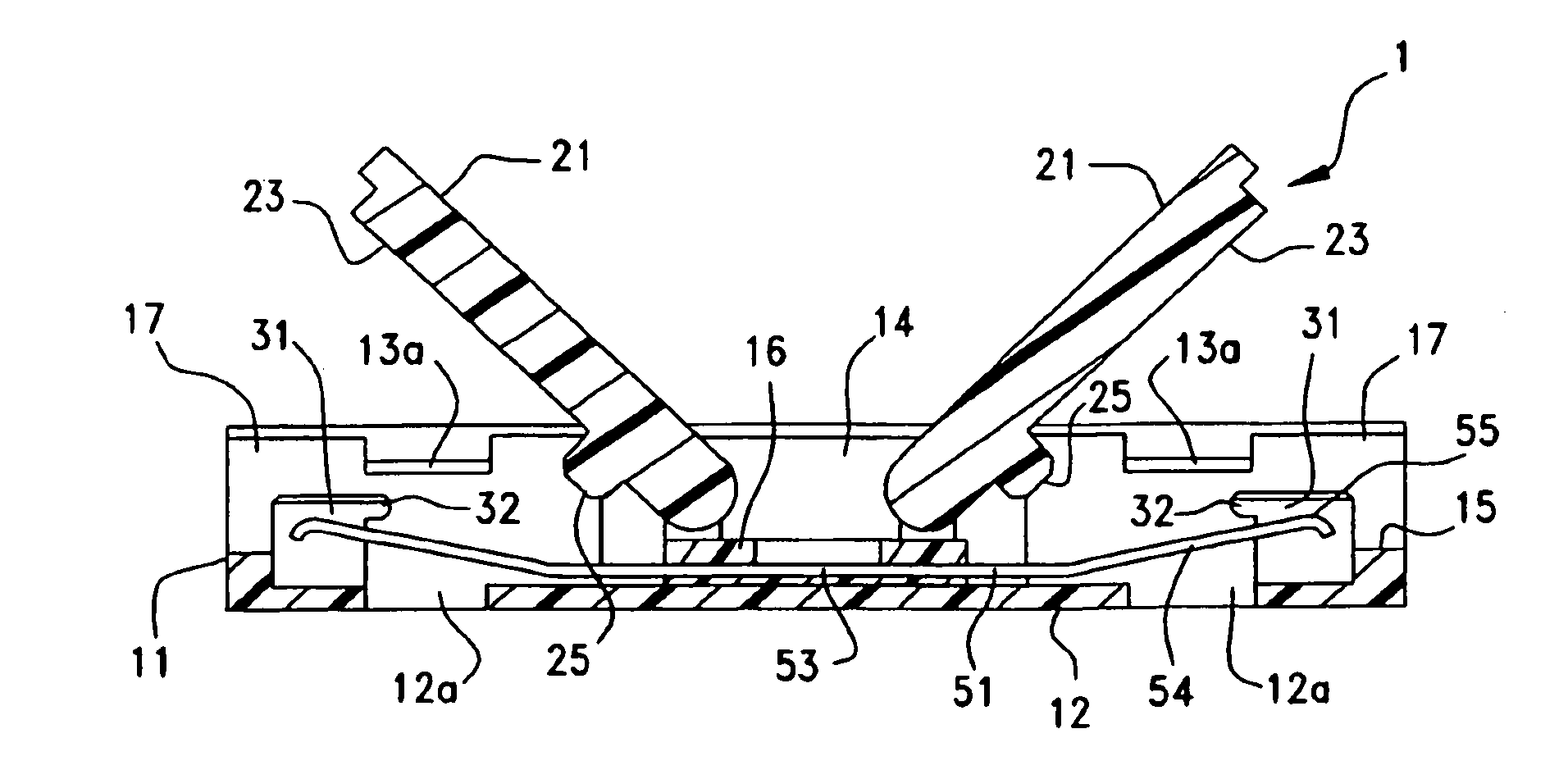
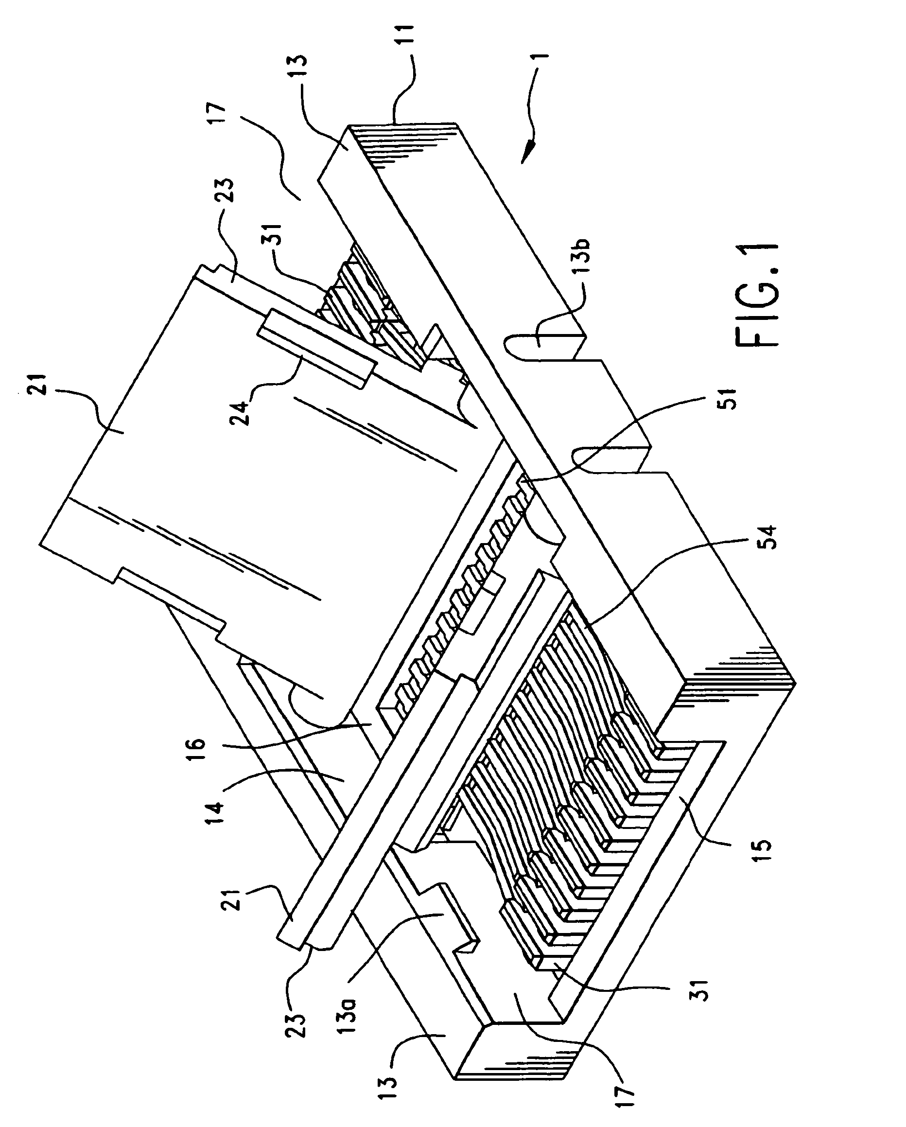
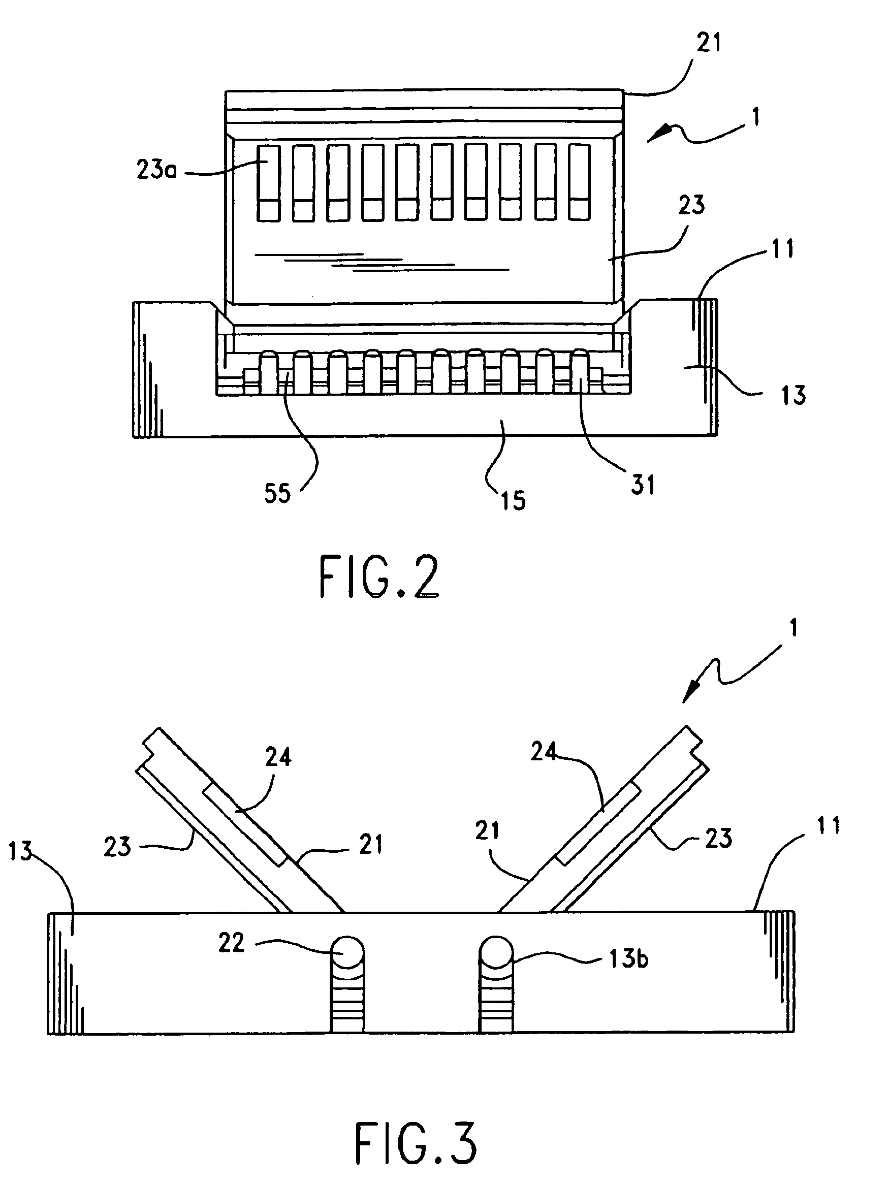
[0036]In the Figures, reference numeral 1 designates a connector as a relay connector in the present invention, and the connector 1 is used for mutually and electrically connecting a pair of flat cables 101, which will be described later. The flat cable 101 is a flat plate-like flexible cable referred to as a flexible printed circuit (FPC), a flexible flat cable (FFC), or the like, but any type of cable may be used as long as it is a flat cable including conductive wires.

[0037]In this embodiment, representations of directions such as up, down, left, right, front, rear, and the like, used for explaining the structure and movement of each part of the connector 1, are not absolute, but relative. These representations are appropriate when the connector 1 is in the position shown in the figures. If the position of the connector 1 changes, however, it is assumed that these representations are to be changed according to the change of the position of connector 1.

[0038]The connector 1 has an...

second embodiment

[0070]In the second embodiment, representations of directions such as up, down, left, right, front, rear, and the like, used for explaining the structure and movement of each part of the connector 201, are not absolute, but relative. These representations are appropriate when the connector 201 is in the position shown in the figures. If the position of the connector 201 changes, however, it is assumed that these representations are to be changed according to the change of the position of connector 201.

[0071]Here, the connector 201 includes a pair of housings 211. Similar to the housing 11 according to the first embodiment, the housing 211 is a flat plate-like member which is integrally made of an insulating material such as a synthetic resin, for instance, the housing 211 is made of a plastic such as PBT, PC, LCP, PPS, polyamide, PEEK, or the like, and is integrally molded by a method such as injection molding. The housing 211 may be made of any material and molded by any molding me...


PUM


Abstract

A connector (1) comprises a housing (11) including a base plate portion (12) facing one surface of a pair of flat cables (101), and a plurality of terminals (51) for contacting conductive wires of the flat cables, wherein the base plate portion includes a plurality of hook members (31) disposed side by side with the terminals for engaging with engaging holes (112) of the flat cable.

Description

BACKGROUND OF THE INVENTION[0001]The present invention relates to a connector.[0002]Conventionally, a connector for connecting flexible flat cables referred to as flexible circuit boards, flexible flat cables, or the like, is known and described in Japanese Patent Application Laid-Open Publication (Kokai) No. 2002-170613. FIG. 18 is a perspective view of such a conventional connector.[0003]Reference numeral 803 designates a flat cable which includes a base film made of an insulating material such as a synthetic resin or the like, and a plurality of conductive wires 804 made of a conductive material such as metal or the like, and supported by the base film. The coating of the conductive wires 804 is removed in the end portion of the flat cable 803, and the conductive wires 804 are exposed on one surface, the lower surface in FIG. 8. Slits 805 are formed in the end portion of the flat cable 803 between adjacent conductive wires 804 and extend through the base film.[0004]Numeral 800 de...

Claims


Application Information

Patent Timeline
Patent Type & Authority Patents(United States)
IPC IPC(8): H01R12/77H01R12/78
CPCH01R12/774H01R12/78H01R12/88H01R13/58
Inventor NIITSU, TOSHIHIRO
Owner MOLEX INC
Why Eureka
Try Eureka