Electric terminal device and method of connecting the same

a technology of electric terminals and terminals, applied in the direction of optics, instruments, printed circuit aspects, etc., can solve the problems of difficult alignment, experience and time for sophisticated alignment, etc., and achieve the effect of easy and sure connection

Active Publication Date: 2015-03-10
JAPAN DISPLAY CENTRAL CO LTD
View PDF7 Cites 0 Cited by
  • Summary
  • Abstract
  • Description
  • Claims
  • Application Information

AI Technical Summary

Benefits of technology

[0007]Accordingly, it is an object of the present invention to provide an electric terminal device in which electric terminals of a primary substrate are easily connected to those of a tape substrate and a method of connecting the electric terminals.
[0010]According to the present invention, since a part of the tape-side electric terminals is used for a terminal or terminals to align with a part of the primary-substrate-side electric terminals, the tape-side electric terminals are easily and surely connected.

Problems solved by technology

Thus, such sophisticated alignment requires experience and time; the problem is that the alignment is not easy.

Method used


Image

  • Electric terminal device and method of connecting the same
  • Electric terminal device and method of connecting the same
  • Electric terminal device and method of connecting the same

Examples


embodiment

[0016]An embodiment of the present invention will be described below with reference to FIGS. 1 and 2.

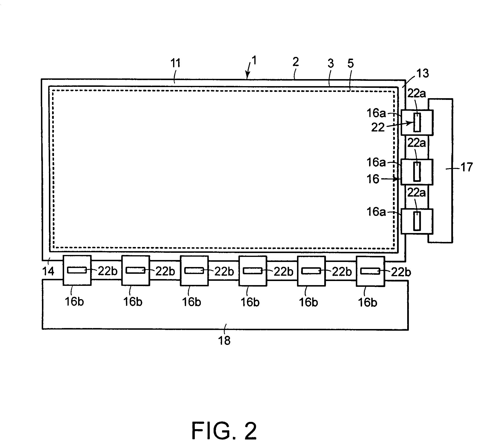
[0017]FIG. 2 is a partial plan view of an LCD apparatus. The LCD apparatus includes an active matrix type LCD cell 1 provided with pixel array substrate 2 as a first substrate, counter substrate 3 as a second substrate, and a liquid crystal (LC) layer, not shown. Sealants set along circumferences of LCD cell 1 fix counter substrate 3 on pixel array substrate 2, so that the LC layer is held between array substrate 2 and counter substrate 3. A central area of LCD cell 1 is provided with rectangular effective display portion 5 capable of displaying images. Pixels, not shown, are disposed longitudinally and laterally to form a matrix structure on LCD cell 1.

[0018]Pixel array substrate 2 is provided with glass substrate 11 as a transparent insulating substrate. Signal and scanning lines, not shown, are disposed to cross each other at right angle on a surface of pixel array substrate 2. Ea...


PUM


Abstract

An electric terminal device is provided with glass substrate 11, glass-substrate-side electric terminals 15 formed on glass substrate 11, tape carrier packages 16a and 16b which are larger in thermal expansion rate than glass substrate 11, and tape-side electric terminals 21 provided to correspond to glass-substrate-side electric terminals 15. Tape-side electric terminals 21 include alignment terminals 25 to align with terminals at the outer most edges of glass-substrate-side electric terminals 15, and connecting terminals 26 electrically and mechanically connected to glass-substrate-side electric terminals 15 due to thermal expansion of tape carrier packages 16a and 16b by thermo-compression bonding on a condition that alignment terminals 25 of tape-side electric terminals 21 are aligned with the terminals of glass-substrate-side electric terminals 15.

Description

CROSS-REFERENCE OF RELATED APPLICATIONS[0001]This application is based upon and claims the benefit of priority from the prior Japanese Patent Application No. 2006-115946, filed on Apr. 19, 2006, the entire contents of which are incorporated herein by reference.FIELD OF THE INVENTION[0002]This invention generally relates to an electric terminal device provided for connecting terminals formed on a base member to a plurality of electric terminals disposed on a tape substrate that is larger in thermal expansion rate than the base member and a method of connecting the same.BACKGROUND OF THE INVENTION[0003]Conventionally, a liquid crystal display (LCD) apparatus, as an example of a flat display apparatus, includes a base member, such as a glass substrate, pixels including pixel electrodes and thin-film transistor (TFT) switching elements disposed in a matrix on the substrate to form an LCD panel or an LCD cell, polyimide flexible tape substrates, such as tape-carrier-package (TCP) members...

Claims


Application Information

Patent Timeline
Patent Type & Authority Patents(United States)
IPC IPC(8): H01L23/48H05K1/11H05K3/36
CPCH05K3/361H05K1/117H05K2201/068H05K2201/09781H05K2203/0278H05K2203/166H01L2924/0002H01L2924/00
Inventor ICHIYAMA, IWANE
Owner JAPAN DISPLAY CENTRAL CO LTD
Why Eureka
Try Eureka